Nissan Primera P12. Manual — part 529
LAN-28
[CAN]
CAN SYSTEM (TYPE 22)
CAN SYSTEM (TYPE 22)
PFP:23710
System Description
EKS00AQF
CAN (Controller Area Network) is a serial communication line for real time application. It is an on-vehicle mul-
tiplex communication line with high data communication speed and excellent error detection ability. Many elec-
tronic control units are equipped onto a vehicle, and each control unit shares information and links with other
control units during operation (not independent). In CAN communication, control units are connected with 2
communication lines (CAN H line, CAN L line) allowing a high rate of information transmission with less wiring.
Each control unit transmits/receives data but selectively reads required data only.
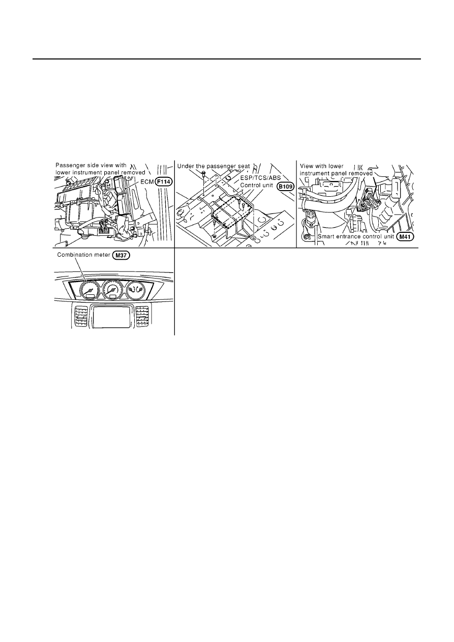
Component Parts and Harness Connector Location
EKS00AQG
PKIA1471E
CAN SYSTEM (TYPE 22)
LAN-29
[CAN]
C
D
E
F
G
H
I
J
L
M
A
B
LAN
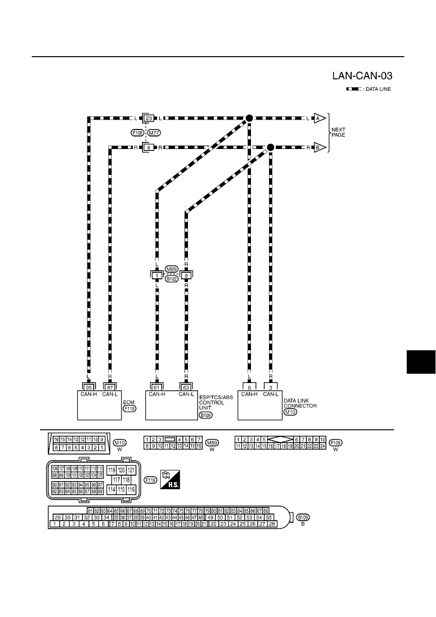
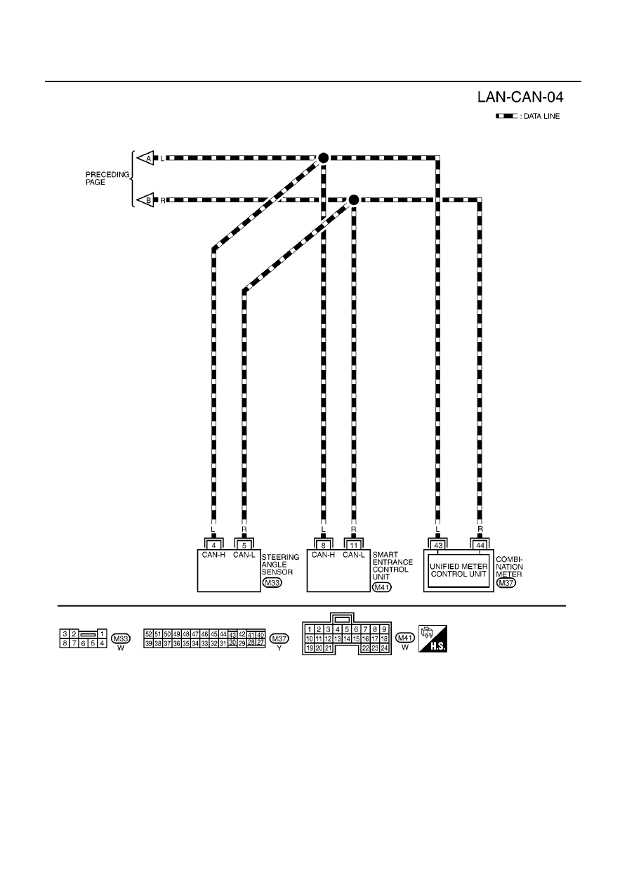
Wiring Diagram — CAN —
EKS00AQH
MKWA1717E
LAN-30
[CAN]
CAN SYSTEM (TYPE 22)
MKWA1718E
CAN SYSTEM (TYPE 22)
LAN-31
[CAN]
C
D
E
F
G
H
I
J
L
M
A
B
LAN
Work Flow
EKS00AQI
1.
Print all the data of “SELF-DIAG RESULTS” and “DATA MONITOR” for “ENGINE”, “ABS”, and “SMART
ENTRANCE” displayed on CONSULT-II.Refer to the following:
●
EC-83, "DTC U1000 CAN COMMUNICATION LINE"
for “ENGINE”
●
for “ABS”
●
BCS-23, "CAN Communication Line Check"
for “SMART ENTRANCE”
2.
Attach the printed sheet of “SELF-DIAG RESULTS” and “DATA MONITOR” onto the check sheet. Refer to
.
3.
Based on the data monitor results, put “v” marks onto the items with “UNKWN” or “NG” in the check sheet
table. Refer to
.
NOTE:
If “NG” is displayed on “CAN COMM” for the diagnosed control unit, replace the control unit.
4.
According to the check sheet results (example), start inspection. Refer to
.
Нет комментариевНе стесняйтесь поделиться с нами вашим ценным мнением.
Текст