Nissan Primera P12. Manual — part 341
DTC P0642, P0643 SENSOR POWER SUPPLY
EC-549
[YD (WITHOUT EURO-OBD)]
C
D
E
F
G
H
I
J
K
L
M
A
EC
On Board Diagnosis Logic
EBS0159B
The MI will not light up for these self-diagnoses.
DTC Confirmation Procedure
EBS0159C
NOTE:
If DTC Confirmation Procedure has been previously conducted, always turn ignition switch OFF and wait at
least 10 seconds before conducting the next test.
WITH CONSULT-II
1.
Turn ignition switch ON.
2.
Select “DATA MONITOR” mode with CONSULT-II.
3.
Wait at least 5 seconds.
4.
If DTC is detected, go to
EC-551, "Diagnostic Procedure"
.
91
W
Accelerator pedal position
sensor 2
[Ignition switch ON]
●
Engine stopped
●
Accelerator pedal fully released
0.4 - 0.7V
[Ignition switch ON]
●
Engine stopped
●
Accelerator pedal fully depressed
2.2 - 2.7V
92
B
Accelerator pedal position
sensor 2 ground
[Ignition switch ON]
Approximately 0.3V
TERMI-
NAL
NO.
WIRE
COLOR
ITEM
CONDITION
DATA
(DC Voltage)
DTC No.
Trouble diagnosis name
DTC detecting condition
Possible cause
P0642
Accelerator pedal position
sensor 1 power supply cir-
cuit low
ECM detects a voltage of power source for the
APP sensor 1 is excessively low.
●
Harness or connectors
(The APP sensor 1 power supply cir-
cuit is open or shorted.)
●
Accelerator pedal position sensor
(Accelerator pedal position sensor 1)
P0643
Accelerator pedal position
sensor 1 power supply cir-
cuit high
ECM detects a voltage of power source for the
APP sensor 1 is excessively high.
SEF817Y
EC-550
[YD (WITHOUT EURO-OBD)]
DTC P0642, P0643 SENSOR POWER SUPPLY
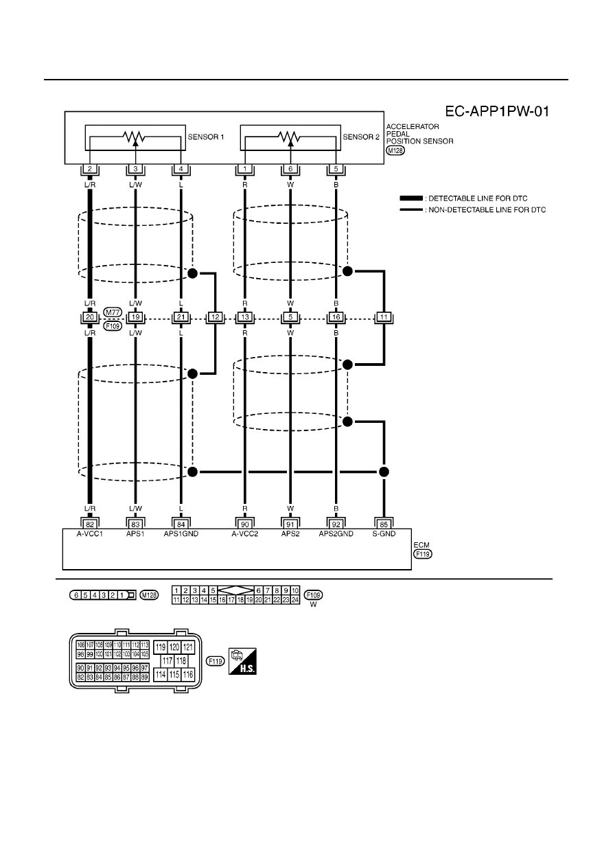
Wiring Diagram
EBS0159D
MBWA0434E
DTC P0642, P0643 SENSOR POWER SUPPLY
EC-551
[YD (WITHOUT EURO-OBD)]
C
D
E
F
G
H
I
J
K
L
M
A
EC
Diagnostic Procedure
EBS0159E
1.
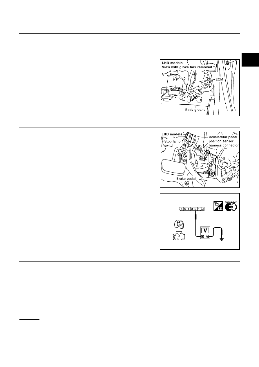
CHECK GROUND CONNECTIONS
1.
Turn ignition switch OFF.
2.
Loosen and retighten engine ground screws. Refer to
.
OK or NG
OK
>> GO TO 2.
NG
>> Repair or replace ground connections.
2.
CHECK APP SENSOR 1 POWER SUPPLY CIRCUIT
1.
Disconnect accelerator pedal position (APP) sensor harness
connector.
2.
Turn ignition switch ON.
3.
Check voltage between APP sensor terminal 2 and ground with
CONSULT-II or tester.
OK or NG
OK
>> GO TO 4.
NG
>> GO TO 3.
3.
DETECT MALFUNCTIONING PART
Check the following.
●
Harness connectors M77, F109
●
Harness for open or short between ECM and APP sensor
>> Repair open circuit or short to ground or short to power in harness or connectors.
4.
CHECK APP SENSOR
Refer to
EC-552, "Component Inspection"
.
OK or NG
OK
>> GO TO 5.
NG
>> Replace accelerator pedal assembly.
MBIB0915E
MBIB0903E
Voltage: Approximately 5.3V
PBIB0811E
EC-552
[YD (WITHOUT EURO-OBD)]
DTC P0642, P0643 SENSOR POWER SUPPLY
5.
CHECK INTERMITTENT INCIDENT
Refer to
EC-408, "TROUBLE DIAGNOSIS FOR INTERMITTENT INCIDENT"
.
>> INSPECTION END
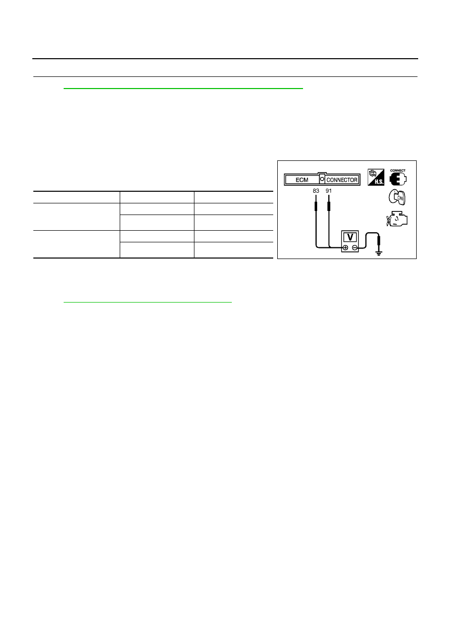
Component Inspection
EBS0159F
ACCELERATOR PEDAL POSITION SENSOR
1.
Reconnect all harness connectors disconnected.
2.
Turn ignition switch ON.
3.
Check voltage between ECM terminals 83 (APP sensor 1 sig-
nal), 91 (APP sensor 2 signal) and body ground under the fol-
lowing conditions.
4.
If NG, replace accelerator pedal assembly.
Removal and Installation
EBS0159G
ACCELERATOR PEDAL
Refer to
ACC-2, "ACCELERATOR CONTROL SYSTEM"
.
Terminal
Accelerator pedal
Voltage
83
(Accelerator pedal position
sensor 1)
Fully released
0.5 - 1.0V
Fully depressed
4.2 - 5.2V
91
(Accelerator pedal position
sensor 2)
Fully released
0.4 - 0.7V
Fully depressed
2.2 - 2.7V
MBIB0615E
Нет комментариевНе стесняйтесь поделиться с нами вашим ценным мнением.
Текст