Nissan Primera P12. Manual — part 79
POWER DOOR LOCK SYSTEM
BL-25
C
D
E
F
G
H
J
K
L
M
A
B
BL
CONSULT- II Application Items
EIS005GV
DOOR LOCKING
DATA MONITOR
WORK SUPPORT
TRUNK RELEASE
DATA MONITOR
WORK SUPPORT
Trouble Diagnoses
EIS005GW
First perform the “SELF-DIAG RESULTS” in “SMART ENTRANCE” with CONSULT-II, when perform the each
trouble diagnosis. Refer to
BCS-13, "CONSULT-II INSPECTION PROCEDURE"
.
SYMPTOM CHART
Monitored Item
Description
IGNITION SW
Indicates [ON/OFF] condition of ignition switch.
KEY IN DETECT
Indicates [ON/OFF] condition of key switch.
DOOR SW DR RR
Indicates [ON/OFF] condition of rear door switch (driver side).
DOOR SW AS RR
Indicates [ON/OFF] condition of rear door switch (passenger side).
AS DOOR SW
Indicates [ON/OFF] condition of front door switch (passenger side).
DR DOOR SW
Indicates [ON\OFF] condition of front door switch (driver side).
CDL LOCK SW
Indicates [ON/OFF] condition of lock signal from door lock/ unlock switch.
CDL UNLOCK SW
Indicates [ON/OFF] condition of unlock signal from door lock/ unlock switch.
RKE LOCK
Indicates [ON/OFF] condition of lock signal from remote controller.
RKE UNLOCK
Indicates [ON/OFF] condition of unlock signal from remote controller.
RKE SEL UNLOCK
Indicates [ON/OFF] condition of select unlock signal from remote controller.
Monitored Item
Description
AUTO RE-LOCK
Auto re-lock function can be changed in this mode. The re-lock mode will be changed when
“CHANGE MODE” on CONSULT-II screen is touched.
SELECTIVE UNLOCK
Selective unlock function can be changed in this mode. The unlock mode will be changed when
“CHANGE SET” on CONSULT-II screen is touched.
Monitored Item
Description
IGNITION SW
Indicates [ON/OFF] condition of ignition switch.
TRUNK OPEN SW
Indicates [ON/OFF] condition of trunk room lamp switch (sedan) or back door switch (wagon).
INT TRUNK REL
Indicates [ON/OFF] condition of internal trunk release switch (sedan) or internal back door
release switch (wagon).
EXT TRUNK REL
Indicates [ON/OFF] condition of external trunk release switch (sedan) or external back door
release switch (wagon).
RKE TRUNK REL
Indicates [ON/OFF] condition of trunk (sedan) or back door (back door) open signal from trunk
or back door release switch.
Monitored Item
Description
TRUNK OPEN DELAY
This mode can be changed trunk release switch (sedan) or back door (wagon) release switch
operation time.
Symptom
Malfunctioning system
Reference
page
Power door lock does not operate using any switch
1.
Smart entrance control unit power supply and ground
circuit check
2.
Door lock actuator check
3.
Replace smart entrance control unit.
—
BL-26
POWER DOOR LOCK SYSTEM
*:Make sure the power door lock system operates properly.
Smart Entrance Control Unit Power Supply and Ground Circuit Check
EIS005GX
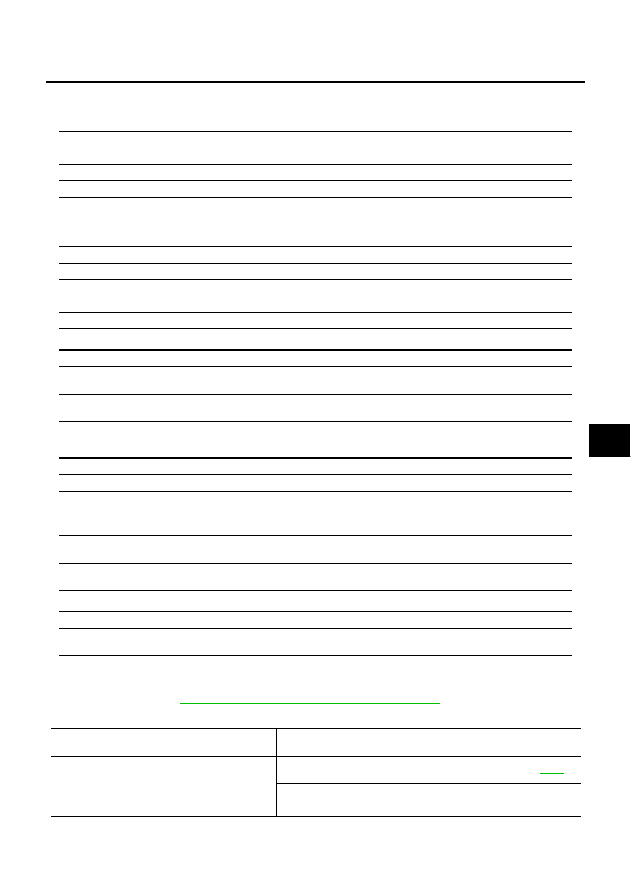
1.
CHECK POWER SUPPLY CIRCUIT
1.
Turn ignition switch OFF.
2.
Disconnect smart entrance control unit connector.
3.
Check voltage between smart entrance control unit harness connector M43 terminal 49, 56 and ground.
OK or NG
OK
>> GO TO 2.
NG
>> Check the following.
●
40A fusible link (letter B, located in the fusible link and
fuse box)
●
10A fuse (No. 12, located in the fusible link and fuse
box)
●
Condition of circuit breaker-1
●
Harness for open or short smart entrance control unit power supply circuit.
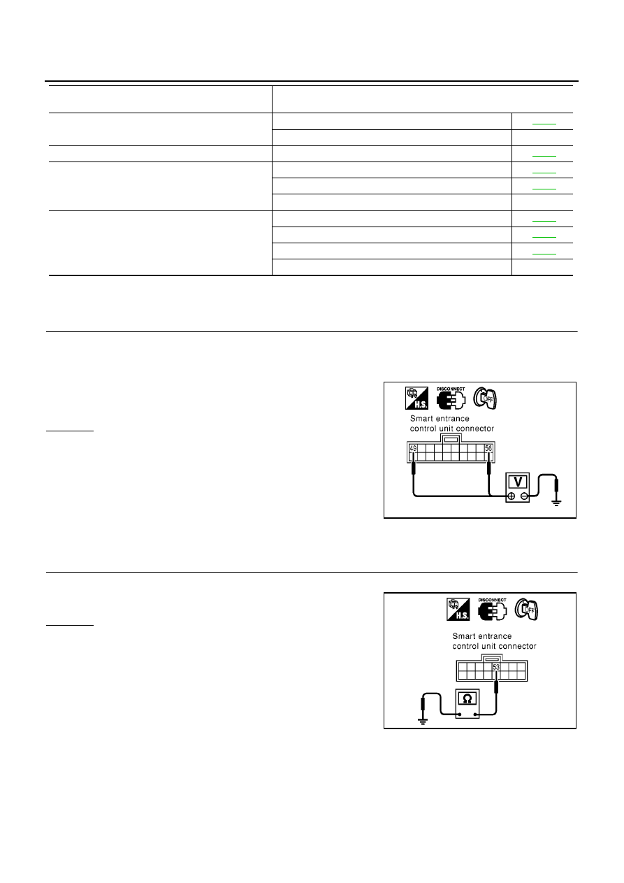
2.
CHECK GROUND CIRCUIT
Check continuity between smart entrance control unit harness connector M43 terminal 53 and ground.
OK or NG
OK
>> Smart entrance control unit power supply and ground
circuit are OK.
NG
>> Check smart entrance control unit ground circuit for
open or short.
Power door lock does not operate with lock/unlock
switch.
1.
Door lock/unlock switch check
2.
Replace smart entrance control unit.
—
Specific door lock actuator does not operate.
1.
Door lock actuator check
*Key reminder system does not operate.
1.
Door switch check
2.
Key switch check
3.
Replace smart entrance control unit.
—
Trunk or back door release actuator does not operate.
1.
Trunk room lamp switch or back door switch check
2.
Trunk release actuator check (sedan)
3.
Back door release actuator check (wagon)
4.
Replace smart entrance control unit.
—
Symptom
Malfunctioning system
Reference
page
49 (W/L) - Ground
: Battery voltage
56 (R/B) - Ground
: Battery voltage
SIIA1564E
53 (B) - Ground
: Continuity should exist.
SIIA1565E
POWER DOOR LOCK SYSTEM
BL-27
C
D
E
F
G
H
J
K
L
M
A
B
BL
Door Lock/Unlock Switch Check
EIS005GY
1.
CHECK DOOR LOCK/UNLOCK SWITCH
WITH CONSULT-II
Check door lock/unlock switch signal (“CDL LOCK SW” or “CDL UNLOCK SW”) in “DATA MONITOR” mode
with CONSULT-II.
WITHOUT CONSULT-II
Check voltage between smart entrance control unit harness connec-
tor and ground.
OK or NG
OK
>> Door lock/unlock switch is OK.
NG
>> GO TO 2.
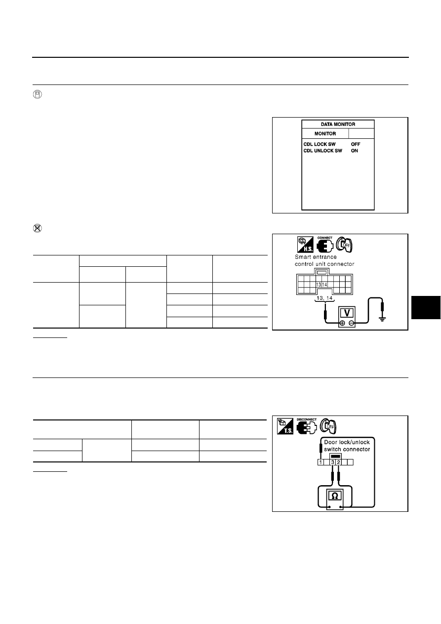
2.
CHECK DOOR LOCK/UNLOCK SWITCH
1.
Turn ignition switch OFF.
2.
Disconnect door lock/unlock switch connector.
3.
Check continuity between door lock/unlock switch connector terminals 1, 2 and 3.
OK or NG
OK
>> Check the following.
●
Ground circuit for door lock/unlock switch
●
Harness for open short between door lock/unlock
switch and smart entrance control unit
NG
>> Replace door lock/unlock switch.
When door lock/unlock is
locked
: CDL LOCK SW ON
When door lock/unlock is
unlocked
: CDL UNLOCK SW ON
MKIB0198E
Connector
Terminals (wire color)
Condition
(Door lock/
unlock switch)
Voltage (V)
(Approx.)
(+)
(
−
)
M41
13 (GY)
Ground
Locked
0
Unlocked
Battery voltage
14 (BR/Y)
Locked
Battery voltage
Unlocked
0
MKIB0582E
Terminal
Door lock/unlock
switch condition
Continuity
1
3
Lock
Yes
2
Unlock
Yes
MKIB0261E
BL-28
POWER DOOR LOCK SYSTEM
Door Lock Actuator Check
EIS005GZ
DRIVER SIDE
1.
CHECK DOOR LOCK SIGNAL
1.
Turn ignition switch OFF.
2.
Disconnect front door lock actuator (driver side) harness connector.
3.
Check voltage between front door lock actuator (driver side) harness connector and ground.
OK or NG
OK
>> Replace front door lock actuator (driver side).
NG
>> GO TO 2.
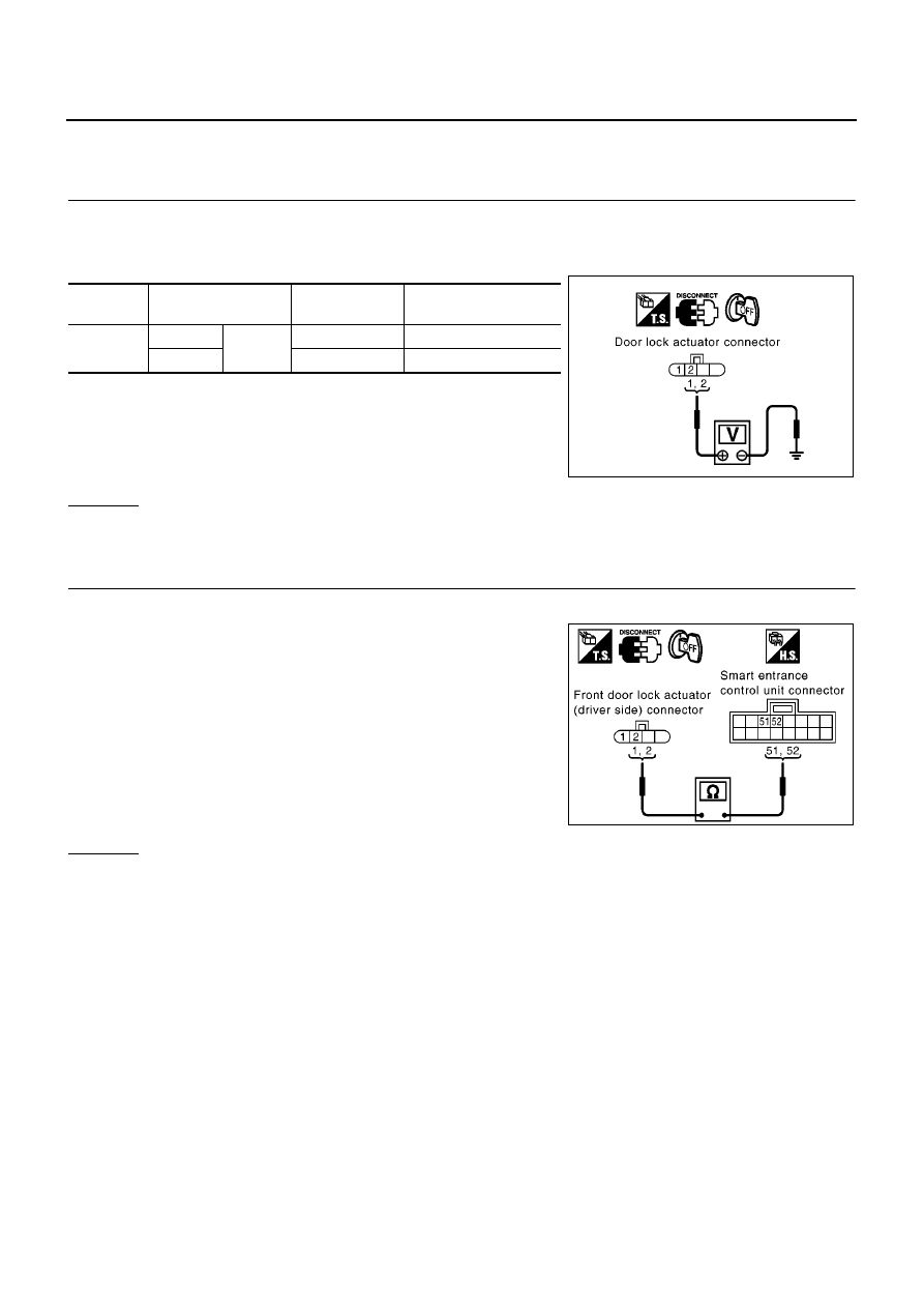
2.
CHECK DOOR LOCK ACTUATOR CIRCUIT
1.
Disconnect smart entrance control unit harness connector.
2.
Check continuity between front door lock actuator (driver side)
harness connector D8 terminal 1, 2 and smart entrance control
unit harness connector M43 terminal 51, 52.
OK or NG
OK
>> Replace smart entrance control unit.
NG
>> Repair or replace harness between smart entrance control unit and front door lock actuator (driver
side).
Connector
Terminal (wire color)
Door lock/unlock
switch condition
Voltage (V)
(Approx.)
D8
1 (L/R)
Ground
Lock
0
→
Battery voltage
→
0
2 (Y)
Unlock
0
→
Battery voltage
→
0
MIIB0451E
1 (L/R) - 51 (L/R)
: Continuity should exist.
2 (Y) - 52 (Y)
: Continuity should exist.
MIIB0452E
Нет комментариевНе стесняйтесь поделиться с нами вашим ценным мнением.
Текст