Nissan Altima HL32 Hybrid. Manual — part 383

EM-46
< ON-VEHICLE REPAIR >
[QR25DE]
CAMSHAFT
• Install No. 1 camshaft bracket as follows.
- Apply sealant to No.1 camshaft bracket as shown.
• Use Genuine Silicone RTV Sealant, or equivalent. Refer to
GI-15, "Recommended Chemical Products and Sealants"
.
CAUTION:
• After installation, be sure to wipe off any excessive seal-
ant leaking from part (A) (both on right and left sides).
• Apply sealant to camshaft bracket contact surface on the front
cover backside.
• Apply sealant to the outside of bolt hole on front cover.
• Position the No.1 camshaft bracket near the mounting posi-
tion, and install it without disturbing the sealant applied to the
surfaces.
4. Tighten camshaft bracket bolts in four steps in the order as
shown.
CAUTION:
After tightening camshaft bracket bolts, be sure to wipe off
excessive sealant from the parts listed below.
• Mating surface of rocker cover.
• Mating surface of front cover, when installed without the front cover.
SBIA0257E
Dimension (A)
: 3.9 mm (0.154 in)
AWBIA0062ZZ
SBIA0259E
Step 1 (bolts 9 - 11) : 1.96 N·m (0.2 kg-m, 17 in-lb)
Step 2 (bolts 1 - 8)
: 1.96 N·m (0.2 kg-m, 17 in-lb)
Step 3 (bolts 1 - 11) : 5.88 N·m (0.6 kg-m, 52 in-lb)
Step 4 (bolts 1 - 11) : 10.4 N·m (1.02 kg-m, 92 in-lb)
SBIA0255E

CAMSHAFT
EM-47
< ON-VEHICLE REPAIR >
[QR25DE]
C
D
E
F
G
H
I
J
K
L
M
A
EM
N
P
O
5. Install camshaft sprockets.
• Install them by lining up the mating marks on each camshaft
sprocket with the ones painted on the timing chain during
removal.
• Before installation of chain tensioner, it is possible to re-match
the marks on timing chain with the ones on each sprocket.
CAUTION:
• Aligned mating marks could slip. Therefore, after match-
ing them, hold the timing chain in place by hand.
• Before and after installing chain tensioner, check again to
make sure that mating marks have not slipped.
6. Install chain tensioner.
CAUTION:
• After installation, pull the stopper pin off completely, and make sure that the tensioner is fully
released.
7. Install chain guide.
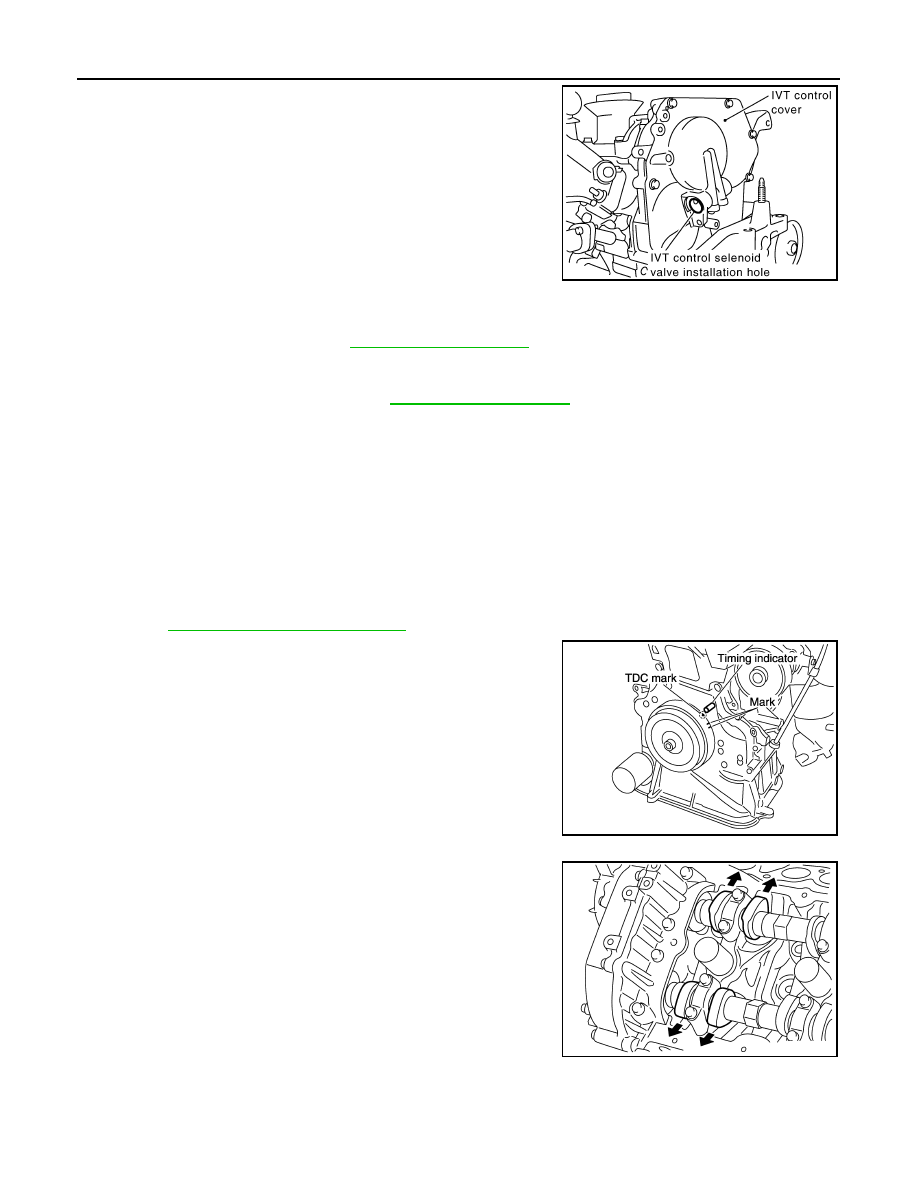
8. Install IVT control cover with the following procedure.
a. Install IVT control solenoid valve to intake valve timing control
cover.
b. Install O-ring to front cover side.
c. Apply Genuine Silicone RTV Sealant to the positions as shown.
Refer to
GI-15, "Recommended Chemical Products and Seal-
d. Install IVT control cover.
• Tighten the bolts in the numerical order as shown.
9. Check and adjust valve clearances. Refer to
.
10. Installation of the remaining components is in the reverse order
as shown.
Inspection After Installation
INFOID:0000000004211250
Inspection of Camshaft Sprocket (INT) Oil Groove
WARNING:
• Check when engine is cold so as to prevent burns from any splashing engine oil.
CAUTION:
• Perform this inspection only when DTC P0011 is detected in self-diagnostic results of CONSULT III
and it is directed according to inspection procedure of EC section. Refer to
1. Check engine oil level. Refer to
.
2. Perform the following procedure so as to prevent the engine from being unintentionally started while
checking.
a. Release fuel pressure. Refer to
.
b. Disconnect ignition coil and injector harness connectors if practical.
3. Remove IVT control solenoid valve. Refer to
EM-51, "Removal and Installation"
.
Diameter (A)
: 3.0 - 4.0 mm (0.118 - 0.157 in)
KBIA0115E
ALBIA0193ZZ
ALBIA0192ZZ
EM-48
< ON-VEHICLE REPAIR >
[QR25DE]
CAMSHAFT
4. Crank engine, and then make sure that engine oil comes out
from IVT control cover oil hole. End cranking after checking.
WARNING:
Be careful not to touch rotating parts (drive belts, idler pul-
ley, and crankshaft pulley, etc.).
CAUTION:
• Engine oil may squirt from IVT control solenoid valve
installation hole during cranking. Use a shop cloth to pre-
vent engine oil from splashing on worker, engine compo-
nents and vehicle.
• Do not allow engine oil to get on rubber components such
as drive belts or engine mount insulators. Immediately
wipe off any splashed engine oil.
5. Clean oil groove between oil strainer and IVT control solenoid valve if engine oil does not come out from
IVT control cover oil hole. Refer to
.
6. Remove components between IVT control solenoid valve and camshaft sprocket (INT), and then check
each oil groove for clogging.
• Clean oil groove if necessary. Refer to
7. After inspection, installation of the remaining components is in the reverse order of removal.
Valve Clearance
INFOID:0000000004211251
Inspection
• Perform this inspection as follows after removal, installation, or replacement of the camshaft or any valve-
related parts, or if there are any unusual engine conditions due to changes in valve clearance over time
(starting, idling, and/or noise).
1. Warm up the engine, then stop it.
2. Remove front RH engine under cover using power tool.
3. Remove the rocker cover using power tool.
EM-38, "Removal and Installation"
4. Turn crankshaft pulley in normal direction (clockwise when
viewed from front) to align TDC identification mark (without paint
mark) with timing indicator.
5. At this time, check that the both intake and exhaust cam lobes of
No. 1 cylinder face outside.
• If they do not face outside, turn crankshaft pulley once more.
KBIA2683E
KBIA0190E
KBIA0400J

CAMSHAFT
EM-49
< ON-VEHICLE REPAIR >
[QR25DE]
C
D
E
F
G
H
I
J
K
L
M
A
EM
N
P
O
6. By referring to the figure (locations indicated with black arrow),
measure valve clearances with a feeler gauge at locations
marked X as shown in the table below.
• No.1 cylinder compression TDC.
• Use a feeler gauge to measure the clearance between valve
and camshaft.
*Reference data at approximately 80
°C (176°F)
CAUTION:
If inspection was carried out with cold engine, check that values with fully warmed up engine are
still within specifications.
7. Turn crankshaft one complete revolution (360
°) and align mark on crankshaft pulley with pointer.
8. By referring to the figure (locations indicated with black arrow),
measure valve clearances with a feeler gauge at locations
marked X as shown in the table below.
• No.4 cylinder compression TDC.
9. If out of specifications, adjust as follows.
ADJUSTMENT
• Perform adjustment depending on selected head thickness of valve lifter.
• The specified valve lifter thickness is the dimension at normal temperatures. Ignore dimensional differences
caused by temperature. Use the specifications for hot engine condition to adjust.
1. Remove camshaft. Refer to
EM-40, "Removal and Installation"
2. Remove the valve lifters at the locations that are outside the standard.
Cylinder
No.1
No.2
No.3
No.4
Valve
INT
EXH
INT
EXH
INT
EXH
INT
EXH
Measurable
×
×
×
x
KBIA0248E
Valve clearance standard:
Cold
Intake
: 0.24 - 0.32 mm (0.009 - 0.013 in)
Exhaust
: 0.26 - 0.34 mm (0.010 - 0.013 in)
Hot*
Intake
: 0.304 - 0.416 mm (0.012 - 0.016 in)
Exhaust
: 0.308 - 0.432 mm (0.012 - 0.017 in)
Cylinder
No.1
No.2
No.3
No.4
Valve
INT
EXH
INT
EXH
INT
EXH
INT
EXH
Measurable
x
×
x
×
KBIA0185E
KBIA0249E
Нет комментариевНе стесняйтесь поделиться с нами вашим ценным мнением.
Текст