Nissan Altima HL32 Hybrid. Manual — part 671

P0AA7-727
HBC-433
< COMPONENT DIAGNOSIS >
D
E
F
G
H
I
J
K
L
M
A
B
HBC
N
O
P
P0AA7-727
Description
INFOID:0000000004212053
The hybrid vehicle control ECU monitors the insulation monitoring circuit located in the battery smart unit and
detects a malfunction.
DTC Logic
INFOID:0000000004212054
DTC DETECTION LOGIC
Diagnosis Procedure
INFOID:0000000004212055
1.
PRECONDITIONING
• Before inspecting the high-voltage system or disconnecting the low voltage connector of the inverter with
converter assembly, take safety precautions such as wearing insulated gloves and removing the service
plug grip to prevent electrical shocks. After removing the service plug grip, put it in your pocket to prevent
other technicians from accidentally reconnecting it while you are working on the high-voltage system.
• After disconnecting the service plug grip, wait for at least 10 minutes before touching any of the high-voltage
connectors or terminals.
• Waiting for at least 10 minutes is required to discharge the high-voltage capacitor inside the inverter with
converter assembly.
>> GO TO 2.
2.
REPLACE BATTERY SMART UNIT
HBB-101, "Removal and Installation"
>> COMPLETED
DTC No.
INF code
Trouble diagnosis name
DTC detecting condition
Possible cause
P0AA7
727
Hybrid Battery Voltage Isolation
Sensor Circuit
Malfunction in the insulation
monitoring circuit located in the
battery smart unit
Battery smart unit
HBC-434
< COMPONENT DIAGNOSIS >
P0AC0-817
P0AC0-817
Description
INFOID:0000000004212056
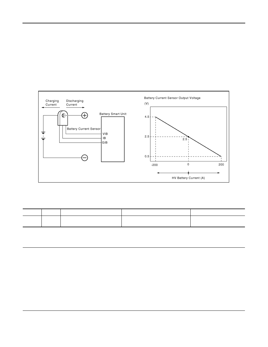
The battery current sensor, which is located in the HV battery junction block on the positive side of the HV bat-
tery, detects the amperage that flows to and from the HV battery. The battery smart unit receives a voltage of
between 0 and 5 V that is in proportion to the amperage flowing in the cable. This voltage goes into the IB ter-
minal from the battery current sensor. A battery current sensor output voltage below 2.5 V indicates that the
HV battery is being charged, and a voltage above 2.5 V indicates that the HV battery is being discharged. The
hybrid vehicle control ECU determines the amount of either charge or discharge amperage that is being
received by the HV battery assembly based on the signals that are input to terminal IB of the battery smart unit
from the battery current sensor. The hybrid vehicle control ECU also calculates the SOC (state of charge) of
the HV battery based on the accumulated amperage.
DTC Logic
INFOID:0000000004212057
DTC DETECTION LOGIC
Diagnosis Procedure
INFOID:0000000004212058
1.
PRECONDITIONING
• Before inspecting the high-voltage system or disconnecting the low voltage connector of the inverter with
converter assembly, take safety precautions such as wearing insulated gloves and removing the service
plug grip to prevent electrical shocks. After removing the service plug grip, put it in your pocket to prevent
other technicians from accidentally reconnecting it while you are working on the high-voltage system.
• After disconnecting the service plug grip, wait for at least 10 minutes before touching any of the high-voltage
connectors or terminals.
• Waiting for at least 10 minutes is required to discharge the high-voltage capacitor inside the inverter with
converter assembly.
>> GO TO 2.
2.
CHECK DTC OUTPUT (HYBRID SYSTEM)
1. Turn ignition switch ON.
2. Check DTC.
JMCIA0090GB
DTC No. INF code
Trouble diagnosis name
DTC detecting condition
Possible cause
P0AC0
817
Hybrid battery pack current sensor
circuit range/performance
HV battery current sensor performance
problem
• HV relay assembly
• Battery smart unit

P0AC0-817
HBC-435
< COMPONENT DIAGNOSIS >
D
E
F
G
H
I
J
K
L
M
A
B
HBC
N
O
P
A or B
A
>> GO TO 3.
B
>> Go to Diagnosis Procedure relevant to output DTC.
3.
REPLACE HV RELAY ASSEMBLY
HBB-105, "Removal and Installation"
>> GO TO 4.
4.
CLEAR DTC
1. Turn ignition switch ON.
2. Read and record the DTCs and freeze frame data.
3. Clear DTC.
>> GO TO 5.
5.
SIMULATION TEST
1. Turn ignition switch ON (READY).
2. Drive the vehicle under the similar conditions to freeze frame data.
>> GO TO 6.
6.
CHECK DTC OUTPUT (HYBRID SYSTEM)
1. Stop vehicle.
2. Check DTC again.
A or B
A
>> INSPECTION END
B
>> Replace battery smart unit (See
HBB-101, "Removal and Installation"
Result
Proceed to
P0AC0-817 only is output.
A
P0A1F-123 is also output.
B
Result
Proceed to
P0AC0-817 is not output.
A
P0AC0-817 is output again.
B

HBC-436
< COMPONENT DIAGNOSIS >
P0ADB-227, P0ADC-226
P0ADB-227, P0ADC-226
Description
INFOID:0000000004212059
The SMRs (System Main Relay) are the relays that connect or disconnect the high voltage power system in
accordance with commands from the hybrid vehicle control ECU.
The SMR system is composed of three SMRs and one system main resistor. SMRB and SMRG are located on
the HV relay assembly in the battery carrier under the HV battery. SMRP and the system main resistor are
located in the hybrid vehicle converter (DC/DC converter) assembly in the battery carrier.
To connect to the high voltage power system, the vehicle will first turn on SMRP and SMRB to charge the vehi-
cle through the system main resistor. Then, SMRP will be turned off after the SMRG is turned on. To shut off
the high voltage power system, SMRB and SMRG are turned off.
When there is an open in the AMD line or IGCT line, the following DTCs are output:
P0AE6-225 is output first because the time required for diagnosis is the shortest.
Trouble area
Malfunction
DTC
Occurrence condition
Open in AMD line
DC/DC converter malfunction
P0A08-264
May not occur
Open in VLO, short to GND
P0A09-591
May not occur
IDH frequency error
P2519-766
Occurs
Open in SMRP, short to GND
P0AE6-225
Occurs
Open in IGCT line
Open in NODD, short to GND
P0A09-265
Occurs
Open in VLO, short to GND
P0A09-591
Occurs
IDH frequency error
P2519-766
Occurs
Open in SMRP, short to GND
P0AE6-225
Occurs
Нет комментариевНе стесняйтесь поделиться с нами вашим ценным мнением.
Текст