Nissan Altima HL32 Hybrid. Manual — part 542
BOOST CONVERTER CONTROL
HBB-25
< FUNCTION DIAGNOSIS >
D
E
F
G
H
I
J
K
L
M
A
B
HBB
N
O
P
BOOST CONVERTER CONTROL
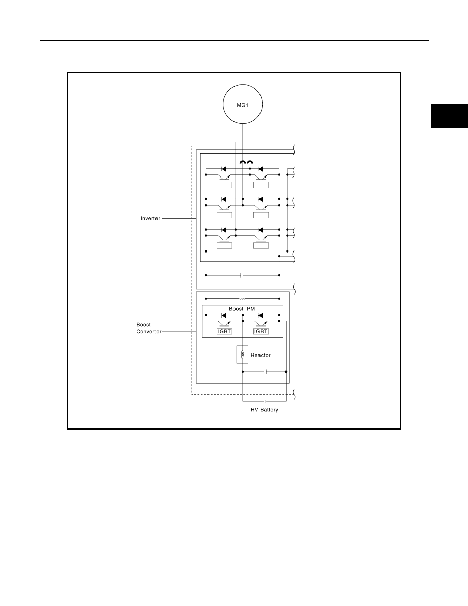
System Diagram
INFOID:0000000004212243
System Description
INFOID:0000000004212244
GENERAL
• The boost converter boosts DC 244.8 V, the nominal voltage of the boost converter, up to a maximum volt-
age of DC 650 V, in accordance with the signals provided by the hybrid vehicle control ECU via the MG
ECU.
• The inverter converts the alternating current generated by MG1 or MG2 into a direct current. The boost con-
verter drops the maximum voltage of DC 650 V to DC 244.8 V, the nominal voltage of the boost converter, in
accordance with the signals provided by the hybrid vehicle control ECU via the MG ECU.
• The boost converter consists of a boost IPM (Intelligent Power Module) with built-in IGBTs (Insulated Gate
Bipolar Transistors) that effect switching control, and a reactor that stores (and charges) electrical power.
VOLTAGE BOOST CONVERSION FUNCTION
• The function of the boost converter to boost DC 244.8 V, the nominal voltage of the boost converter, to max-
imum voltage of DC 650 V flows as described below.
JMCIA0059GB

HBB-26
< FUNCTION DIAGNOSIS >
BOOST CONVERTER CONTROL
• The IGBT (2) turns ON, causing the electrical power of the HV battery to charge the reactor. As a result, the
voltage in the reactor rises.
• In the next stage, when the voltage in the reactor rises to maximum voltage of DC 650 V, the IGBT (2) turns
OFF, causing a counter electromotive force to be created.
• Induced by the counter electromotive force that is created, the electrical power (maximum voltage of DC 650
V) that is charging the reactor flows into the inverter.
VOLTAGE DROP CONVERSION FUNCTION
The alternating current, which is generated by MG1 or MG2 for the purpose of charging the HV battery, is con-
verted into maximum voltage of DC 650 V by the inverter. Then, a function of the boost converter drops the
voltage to DC 244.8 V, the nominal voltage of the boost converter. This is accomplished by the IGBT (1)
switching ON and OFF through duty cycle control, which intermittently interrupts the electrical power provided
by the inverter.
JMCIA0077GB
JMCIA0078GB
JMCIA0079GB

BOOST CONVERTER CONTROL
HBB-27
< FUNCTION DIAGNOSIS >
D
E
F
G
H
I
J
K
L
M
A
B
HBB
N
O
P
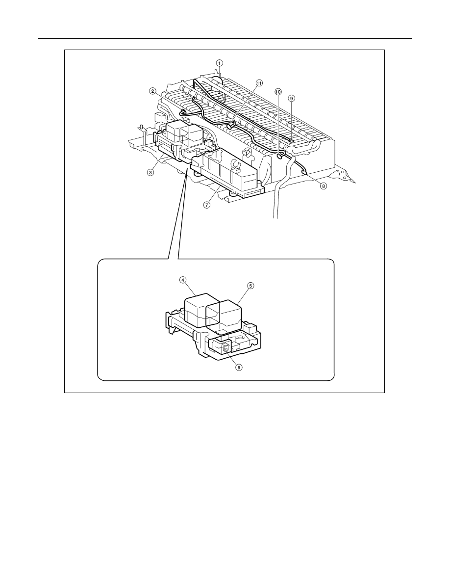
Component Parts Location
INFOID:0000000004212245
1.
Combination meter
2.
HV battery cooling fan
3.
HV battery pack
4.
HV battery cooling fan relay
5.
Hybrid vehicle control ECU
(located under heater box assembly)
ALCIA0003ZZ
HBB-28
< FUNCTION DIAGNOSIS >
BOOST CONVERTER CONTROL
1.
Service plug grip
2.
Battery temperature sensor 0
3.
Battery smart unit
4.
SMRG
5.
SMRB
6.
Battery current sensor
7.
Hybrid vehicle converter
8.
Battery temperature sensor 3
9.
Intake air temperature sensor
10. Battery temperature sensor 2
11. Battery temperature sensor 1
ALCIA0004ZZ
Нет комментариевНе стесняйтесь поделиться с нами вашим ценным мнением.
Текст