Nissan Altima HL32 Hybrid. Manual — part 1000

B2612 STEERING STATUS
SEC-73
< COMPONENT DIAGNOSIS >
[INTELLIGENT KEY SYSTEM]
C
D
E
F
G
H
I
J
L
M
A
B
SEC
N
O
P
1. Turn ignition switch OFF.
2. Disconnect steering lock unit harness connector and IPDM E/R harness connector.
3. Check voltage between steering lock unit harness connector
and ground.
Is the inspection result normal?
YES
>> GO TO 4
NO
>> GO TO 3
3.
CHECK STEERING LOCK UNIT CIRCUIT-I
1. Disconnect BCM harness connector.
2. Check continuity between BCM harness connector M19 (A) ter-
minal 85 and steering lock unit harness connector M32 (B) ter-
minal 3.
3. Check continuity between BCM harness connector M19 (A) ter-
minal 85 and ground.
Is the inspection result normal?
YES
>> GO TO 6
NO
>> Repair harness or connector.
4.
CHECK IPDM E/R OUTPUT SIGNAL
1. Connect IPDM E/R harness connector.
2. Disconnect BCM harness connector.
3. Check voltage between steering lock unit harness connector
and ground.
Is the inspection result normal?
YES
>> Replace steering lock unit.
NO
>> GO TO 5
5.
CHECK STEERING LOCK UNIT CIRCUIT-II
Steering lock unit
Ground
Voltage [V]
Connector
Terminal
M32
3
Ground
Battery voltage
ALKIA0454ZZ
BCM
Steering lock unit
Continuity
Connector
Terminal
Connector
Terminal
A: M19
85
B: M32
3
Yes
BCM
Ground
Continuity
Connector
Terminal
A: M19
85
Ground
No
ALKIA0455ZZ
Steering lock unit
Ground
Voltage [V]
Connector
Terminal
M32
3
Ground
Battery voltage
ALKIA0454ZZ
SEC-74
< COMPONENT DIAGNOSIS >
[INTELLIGENT KEY SYSTEM]
B2612 STEERING STATUS
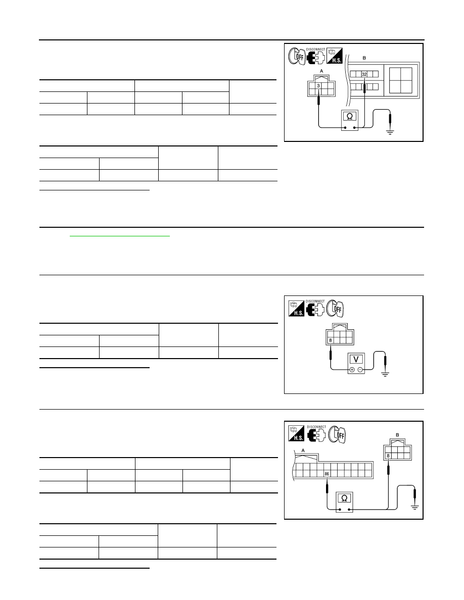
1. Check continuity between steering lock unit harness connector
M32 (A) terminal 3 and IPDM E/R harness connector E17 (B)
terminal 32.
2. Check continuity between steering lock unit harness connector
M32 (A) terminal 3 and ground.
Is the inspection result normal?
YES
>> GO TO 6
NO
>> Repair harness or connector.
6.
CHECK INTERMITTENT INCIDENT
GI-42, "Intermittent Incident"
>> Inspection End.
7.
CHECK BCM OUTPUT SIGNAL
1. Turn ignition switch OFF.
2. Disconnect steering lock unit harness connector and IPDM E/R harness connector.
3. Check voltage between steering lock unit harness connector
and ground.
Is the inspection result normal?
YES
>> GO TO 9
NO
>> GO TO 8
8.
CHECK STEERING LOCK UNIT CIRCUIT-I
1. Disconnect BCM harness connector.
2. Check continuity between BCM harness connector M19 (A) ter-
minal 86 and steering lock unit harness connector M32 (B) ter-
minal 8.
3. Check continuity between BCM harness connector M19 (A) ter-
minal 86 and ground.
Is the inspection result normal?
Steering lock unit
IPDM E/R
Continuity
Connector
Terminal
Connector
Terminal
A: M32
3
B: E17
32
Yes
Steering lock unit
Ground
Continuity
Connector
Terminal
A: M32
3
Ground
No
ALKIA0456ZZ
Steering lock unit
Ground
Voltage [V]
Connector
Terminal
M32
8
Ground
Battery voltage
ALKIA0457ZZ
BCM
Steering lock unit
Continuity
Connector
Terminal
Connector
Terminal
A: M19
86
B: M32
8
Yes
BCM
Ground
Continuity
Connector
Terminal
A: M19
86
Ground
No
ALKIA0458ZZ

B2612 STEERING STATUS
SEC-75
< COMPONENT DIAGNOSIS >
[INTELLIGENT KEY SYSTEM]
C
D
E
F
G
H
I
J
L
M
A
B
SEC
N
O
P
YES
>> GO TO 11
NO
>> Repair harness or connector.
9.
CHECK IPDM E/R OUTPUT SIGNAL
1. Connect IPDM E/R harness connector.
2. Disconnect BCM harness connector.
3. Check voltage between steering lock unit harness connector
and ground.
Is the inspection result normal?
YES
>> Replace steering lock unit.
NO
>> GO TO 10
10.
CHECK STEERING LOCK UNIT CIRCUIT-II
1. Check continuity between steering lock unit harness connector
M32 (A) terminal 8 and IPDM E/R harness connector E18 (B)
terminal 33.
2. Check continuity between steering lock unit harness connector
and ground.
Is the inspection result normal?
YES
>> GO TO 11
NO
>> Repair harness or connector.
11.
CHECK INTERMITTENT INCIDENT
GI-42, "Intermittent Incident"
.
>> Inspection End.
Steering lock unit
Ground
Voltage [V]
Connector
Terminal
M32
8
Ground
Battery voltage
ALKIA0457ZZ
Steering lock unit
IPDM E/R
Continuity
Connector
Terminal
Connector
Terminal
A: M32
8
B: E18
33
Yes
Steering lock unit
Ground
Continuity
Connector
Terminal
A: M32
8
Ground
No
ALKIA0459ZZ

SEC-76
< COMPONENT DIAGNOSIS >
[INTELLIGENT KEY SYSTEM]
B2617 STARTER RELAY CIRCUIT
B2617 STARTER RELAY CIRCUIT
Description
INFOID:0000000004216053
The hybrid system start enabling condition is located in the BCM. BCM transmits the starting signal to HV ECU
via hardwire. HV ECU responds with hybrid system status.
DTC Logic
INFOID:0000000004216054
DTC DETECTION LOGIC
NOTE:
• If DTC B2617 is displayed with DTC U1000, first perform the trouble diagnosis for DTC U1000. Refer to
.
• If DTC B2617 is displayed with DTC U1010, first perform the trouble diagnosis for DTC U1010. Refer to
.
DTC CONFIRMATION PROCEDURE
1.
PERFORM DTC CONFIRMATION PROCEDURE
1. Press the push-button ignition switch under the following conditions.
-
ECVT selector lever is in the P position.
-
Depress the brake pedal.
2. Check “Self diagnostic result” with CONSULT-III.
Is DTC detected?
YES
>> Refer to
.
NO
>> Inspection End.
Diagnosis Procedure
INFOID:0000000004216055
1.
CHECK STARTER RELAY
1. Turn ignition switch ON.
2. Check voltage between BCM harness connector and ground
under the following condition.
Is the measurement value within the specification?
YES
>> GO TO 3
DTC No.
Trouble diagnosis
name
DTC detecting condition
Possible cause
B2617
STARTER RELAY
CIRCUIT
An immediate operation of hybrid starting system is
requested by BCM, but there is no response for
more than 1 second.
• Harness or connectors
(hybrid starting system circuit is
open or shorted.)
• Hybrid vehicle control ECU
ALKIA0452ZZ
BCM
Ground
Condition
Voltage (V)
Connector
Terminal
M21
132
Ground
Ignition
switch
Cranking or request to start (selector lever in P position)
Battery voltage
Other than above
0
Нет комментариевНе стесняйтесь поделиться с нами вашим ценным мнением.
Текст