Nissan Altima HL32 Hybrid. Manual — part 340

EC-344
< COMPONENT DIAGNOSIS >
[QR25DE]
P1564 ASCD STEERING SWITCH
• Harness for open and short between ECM and combination switch
>> Repair open circuit or short to ground or short to power in harness or connectors.
5.
CHECK ASCD STEERING SWITCH INPUT SIGNAL CIRCUIT FOR OPEN AND SHORT
1. Check the continuity between ECM harness connector and combination switch.
2. Also check harness for short to ground and short to power.
Is the inspection result normal?
YES
>> GO TO 7.
NO
>> GO TO 6.
6.
DETECT MALFUNCTIONING PART
Check the following.
• Harness connectors M1, E30
• Combination switch (spiral cable)
• Harness for open and short between ECM and combination switch
>> Repair open circuit or short to ground or short to power in harness or connectors.
7.
CHECK ASCD STEERING SWITCH
EC-344, "Component Inspection"
Is the inspection result normal?
YES
>> GO TO 8.
NO
>> Replace ASCD steering switch.
8.
CHECK INTERMITTENT INCIDENT
GI-42, "Intermittent Incident"
>> INSPECTION END
Component Inspection
INFOID:0000000004211587
1.
CHECK ASCD STEERING SWITCH
1. Disconnect combination switch (spiral cable) harness connector M88.
2. Check the continuity between combination switch harness con-
nector terminals under following conditions.
Is the inspection result normal?
YES
>> INSPECTION END
NO
>> Replace ASCD steering switch
Combination
switch
ECM
Continuity
Terminal
Connector
Terminal
13
E10
85
Existed
Combination meter
Condition
Resistance
Connector
Terminals
M88
13 and 16
MAIN switch: Pressed
Approx. 0
Ω
CANCEL switch: Pressed
Approx. 250
Ω
SET/COAST switch: Pressed
Approx. 660
Ω
RESUME/ACCELERATE switch:
Pressed
Approx. 1,480
Ω
All ASCD steering switches: Released
Approx. 4,000
Ω
JMBIA1625ZZ

P1572 ASCD BRAKE SWITCH
EC-345
< COMPONENT DIAGNOSIS >
[QR25DE]
C
D
E
F
G
H
I
J
K
L
M
A
EC
N
P
O
P1572 ASCD BRAKE SWITCH
Description
INFOID:0000000004211588
When the brake pedal is depressed, ASCD brake switch is turned OFF and stop lamp switch is turned ON.
ECM and hybrid vehicle control ECU detects the state of the brake pedal by this input of two kinds (ON/OFF
for the ASCD function.
DTC Logic
INFOID:0000000004211589
DTC DETECTION LOGIC
NOTE:
• If DTC P1572 is displayed with DTC P0605, first perform the trouble diagnosis for DTC P0605. Refer
.
• This self-diagnosis has the one trip detection logic. When malfunction A is detected, DTC is not
stored in ECM memory. And in that case, 1st trip DTC and 1st trip freeze frame data are displayed.
1st trip DTC is erased when ignition switch OFF. And even when malfunction A is detected in two
consecutive trips, DTC is not stored in ECM memory.
DTC CONFIRMATION PROCEDURE
1.
PRECONDITIONING
If DTC Confirmation Procedure has been previously conducted, always perform the following before conduct-
ing the next test.
1. Turn ignition switch OFF and wait at least 10 seconds.
2. Turn ignition switch ON.
3. Turn ignition switch OFF and wait at least 10 seconds.
TESTING CONDITION:
This test may be conducted with the drive wheels lifted in the shop or by driving the vehicle. If this test
is conducted with the drive wheels lifted, activate “INPSECTION MODE 1” (
). If a road test is
expected to be easier, it is unnecessary to lift up the vehicle.
NOTE:
Procedure for malfunction B is not described here. It takes extremely long time to complete procedure for mal-
function B. By performing procedure for malfunction A, the incident that causes malfunction B can be
detected.
>> GO TO 2.
2.
PERFORM DTC CONFIRMATION PROCEDURE FOR MALFUNCTION A
1. Turn ignition switch ON (READY).
2. Press MAIN switch and make sure that CRUISE indicator is displayed in combination meter.
3. Drive the vehicle for at least 5 consecutive seconds under the following conditions.
CAUTION:
Always drive vehicle at a safe speed.
NOTE:
This procedure may be conducted with the drive wheels lifted in the shop or by driving the vehicle.
If a road test is expected to be easier, it is unnecessary to lift the vehicle.
DTC No.
Trouble diagnosis
name
DTC detecting condition
Possible cause
P1572
ASCD brake switch
A)
When the vehicle speed is above 30 km/h
(19 MPH), ON signals from the stop lamp
switch and the ASCD brake switch are sent
to the ECM at the same time.
• Harness or connectors
(The stop lamp switch circuit is shorted.)
• Harness or connectors
(The ASCD brake switch circuit is shorted.)
• Harness or connectors
• Stop lamp switch
• ASCD brake switch
• Incorrect stop lamp switch installation
• Incorrect ASCD brake switch installation
• ECM
B)
ASCD brake switch signal is not sent to
ECM for extremely long time while the ve-
hicle is driving.
EC-346
< COMPONENT DIAGNOSIS >
[QR25DE]
P1572 ASCD BRAKE SWITCH
4. Check 1st trip DTC.
Is 1st trip DTC detected?
YES
>> Go to
NO
>> GO TO 3.
3.
PERFORM DTC CONFIRMATION PROCEDURE FOR MALFUNCTION B
1. Turn ignition ON (READY) and drive the vehicle for at least 5 consecutive seconds under the following
conditions.
CAUTION:
Always drive vehicle at a safe speed.
NOTE:
This procedure may be conducted with the drive wheels lifted in the shop or by driving the vehicle.
If a road test is expected to be easier, it is unnecessary to lift the vehicle.
2. Check 1st trip DTC.
Is 1st trip DTC detected?
YES
>> Go to
NO
>> INSPECTION END
Diagnosis Procedure
INFOID:0000000004211590
1.
CHECK OVERALL FUNCTION-I
With CONSULT-III
1. Turn ignition switch ON.
2. Select “BRAKE SW1” in “DATA MONITOR” mode with CONSULT-III.
3. Check “BRAKE SW1” indication under the following conditions.
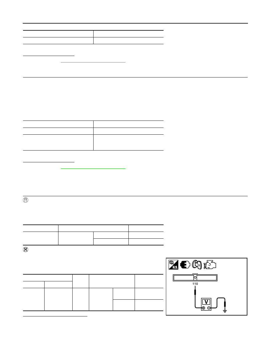
Without CONSULT-III
1. Turn ignition switch ON.
2. Check the voltage between ECM harness connector and
ground.
Is the inspection result normal?
YES
>> GO TO 2.
NO
>> GO TO 3.
VHCL SPEED SE
More than 30 km/h (19 mph)
Shift lever
Suitable position
VHCL SPEED SE
More than 30 km/h (19 mph)
Selector lever
Suitable position
Driving location
Depress the brake pedal for more than
five seconds so as not to come off from
the above-mentioned vehicle speed.
Monitor item
Condition
Indication
BRAKE SW1
Brake pedal
Slightly depressed
OFF
Fully released
ON
ECM
Ground
Condition
Voltage
Connector
Terminal
E10
110
(ASCD brake
switch signal)
Ground Brake pedal
Slightly
depressed
Approx. 0V
Fully
released
Battery voltage
JMBIA1605ZZ

P1572 ASCD BRAKE SWITCH
EC-347
< COMPONENT DIAGNOSIS >
[QR25DE]
C
D
E
F
G
H
I
J
K
L
M
A
EC
N
P
O
2.
CHECK OVERALL FUNCTION-II
With CONSULT-III
Select “BRAKE SW2” and check indication in “DATA MONITOR” mode.
Without CONSULT-III
Check the voltage between ECM harness connector and ground.
Is the inspection result normal?
YES
>> GO TO 13.
NO
>> GO TO 8.
3.
CHECK ASCD BRAKE SWITCH POWER SUPPLY CIRCUIT
1. Turn ignition switch OFF.
2. Disconnect ASCD brake switch harness connector.
3. Turn ignition switch ON.
4. Check the voltage between ASCD brake switch harness con-
nector and ground.
Is the inspection result normal?
YES
>> GO TO 5.
NO
>> GO TO 4.
4.
DETECT MALFUNCTIONING PART
Check the following.
• Fuse block (J/B) connector E6
• Junction block connector E46, E48
• 10A fuse (No.3)
• Harness for open or short between ASCD brake switch and fuse
>> Repair open circuit or short to ground or short to power in harness or connectors.
5.
CHECK ASCD BRAKE SWITCH INPUT SIGNAL CIRCUIT FOR OPEN AND SHORT
1. Turn ignition switch OFF.
2. Disconnect ECM ASCD harness connector.
3. Check the continuity between ASCD brake switch harness connector and ECM harness connector.
4. Also check harness for short to ground and short to power.
Monitor item
Condition
Indication
BRAKE SW2
Brake pedal
Slightly depressed
ON
Fully released
OFF
ECM
Ground
Condition
Voltage
Connector
Terminal
E10
106
(Stop lamp
switch signal)
Ground Brake pedal
Slightly
depressed
Battery voltage
Fully
released
Approx. 0V
PBIB3603E
ASCD brake switch
Ground
Voltage
Connector
Terminal
E37
1
Ground
Battery voltage
PBIB0857E
ASCD brake switch
ECM
Continuity
Connector
Terminal
Connector
Terminal
E37
2
E10
110
Existed
Нет комментариевНе стесняйтесь поделиться с нами вашим ценным мнением.
Текст