Nissan Altima HL32 Hybrid. Manual — part 629

P0A78-286
HBC-265
< COMPONENT DIAGNOSIS >
D
E
F
G
H
I
J
K
L
M
A
B
HBC
N
O
P
OK or NG
OK
>> Replace hybrid transaxle (See
TM-36, "Removal and Installation"
NG
>> Repair or replace harness or connector.
22.
CHECK CONNECTOR CONNECTION CONDITION (MOTOR RESOLVER CONNECTOR)
HBC-171, "Diagnosis Procedure"
OK or NG
OK
>> GO TO 23.
NG
>> CONNECT SECURELY
23.
CHECK HARNESS AND CONNECTOR (INVERTER WITH CONVERTER ASSEMBLY - MOTOR RE-
SOLVER)
HBC-171, "Diagnosis Procedure"
OK or NG
OK
>> Replace hybrid transaxle (See
TM-36, "Removal and Installation"
NG
>> Repair or replace harness or connector.
24.
PERFORM ACTIVE TEST WITH CONSULT-III (INV WATER PUMP)
HBC-362, "Diagnosis Procedure"
OK or NG
OK
>> Add coolant.
NG
>> GO TO 25.
25.
CHECK WATER PUMP WITH MOTOR & BRACKET ASSEMBLY
HBC-362, "Diagnosis Procedure"
OK or NG
OK
>> GO TO 26.
NG
>> GO TO 27.
26.
CHECK HARNESS AND CONNECTOR (WATER PUMP WITH MOTOR & BRACKET ASSEMBLY - HV
CONTROL ECU)
HBC-362, "Diagnosis Procedure"
OK or NG
OK
>> Replace hybrid vehicle control ECU (See
HBC-644, "Removal and Installation"
).
NG
>> Repair or replace harness or connector.
27.
CHECK HIGH VOLTAGE FUSE AND FUSIBLE LINK BOX
.
OK or NG
OK
>> GO TO 28.
NG
>> Replace high voltage fuse and fusible link box.
28.
CHECK HARNESS AND CONNECTOR (WATER PUMP WITH MOTOR POWER SOURCE CIRCUIT)
HBC-362, "Diagnosis Procedure"
OK or NG
OK
>> Replace water pump with motor & bracket assembly.
NG
>> Repair or replace harness or connector.
HBC-266
< COMPONENT DIAGNOSIS >
P0A78-287
P0A78-287
Description
INFOID:0000000004211930
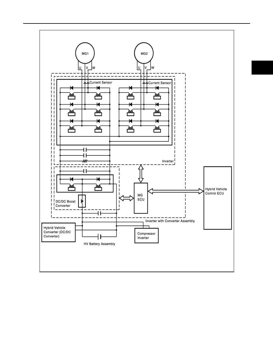
The inverter converts high-voltage direct current from the HV battery and alternating current for MG2 and
MG1. The inverter contains a three-phase bridge circuit, which consists of six power transistors each for MG2
and MG1, that converts direct current to three-phase alternating current. The MG ECU controls the actuation
of the power transistors. The inverter transmits information that is necessary for effecting control, such as the
amperage and voltage, to the MG ECU.
The MG ECU uses a voltage sensor, which is built into the inverter, to detect boosted high voltage to allow
control of the voltage boost.
The inverter voltage sensor outputs voltage that varies between 0 and 5 V in accordance with the changes in
the high voltage. The higher the high voltage, the higher the output voltage, and the lower the high voltage, the
lower the output voltage.
P0A78-287
HBC-267
< COMPONENT DIAGNOSIS >
D
E
F
G
H
I
J
K
L
M
A
B
HBC
N
O
P
The MG ECU monitors the inverter voltage and detects malfunctions.
DTC Logic
INFOID:0000000004211931
DTC DETECTION LOGIC
If MG ECU detects overheat or circuit malfunction of the traction motor inverter, the inverter assembly trans-
mits this information via the traction motor inverter fail signal line.
If excessive amperage flows through the motor inverter due to an internal short, the motor inverter will transmit
an inverter fail signal to the MG ECU. Upon receiving this signal, the hybrid vehicle control ECU will illuminate
the MIL and set a DTC.
JMCIA0099GB

HBC-268
< COMPONENT DIAGNOSIS >
P0A78-287
Diagnosis Procedure
INFOID:0000000004211932
1.
PRECONDITIONING
• Before inspecting the high-voltage system or disconnecting the low voltage connector of the inverter with
converter assembly, take safety precautions such as wearing insulated gloves and removing the service
plug grip to prevent electrical shocks. After removing the service plug grip, put it in your pocket to prevent
other technicians from accidentally reconnecting it while you are working on the high-voltage system.
• After disconnecting the service plug grip, wait for at least 10 minutes before touching any of the high-voltage
connectors or terminals.
• Waiting for at least 10 minutes is required to discharge the high-voltage capacitor inside the inverter with
converter assembly.
>> GO TO 2.
2.
CHECK DTC OUTPUT (HYBRID SYSTEM)
1. Turn ignition switch ON.
2. Check DTC.
NOTE:
P0A78-287 may be set due to a malfunction which also causes DTCs in the table above to be set. In this
case, first troubleshoot the output DTCs in the table above.
Then, perform a test to attempt to reproduce the problems, and check that no DTCs are output.
Is DTC detected?
YES
>> Go to Diagnosis Procedure relevant to output DTC.
NO
>> GO TO 3.
3.
CHECK CONNECTOR CONNECTION CONDITION (INVERTER WITH CONVERTER ASSEMBLY CON-
NECTOR)
See
HBC-109, "Diagnosis Procedure"
OK or NG
OK
>> Replace inverter with converter assembly (See
HBC-638, "Removal and Installation"
).
DTC No.
INF code
Trouble diagnosis name
DTC detecting condition
Possible cause
P0A78
287
Drive Motor “A” Inverter Performance
Motor inverter fail signal detection
(overcurrent due to inverter as-
sembly malfunction)
Inverter with converter assembly
DTC No.
Relevant Diagnosis
P0A1D (Except INF code 390)
Hybrid Powertrain Control Module
P0A1A (all INF codes)
Generator Control Module
P0A1B (all INF codes)
Drive Motor “A” Control Module
P0A72 (all INF codes)
Generator Phase V Current
P0A75 (all INF codes)
Generator Phase W Current
P0A60 (all INF codes)
Drive Motor “A” Phase V Current
P0A63 (all INF codes)
Drive Motor “A” Phase W Current
P0A4B-253
Generator Position Sensor Circuit
P0A4D-255
Generator Position Sensor Circuit Low
P0A4C-513
Generator Position Sensor Circuit Range/Performance
P0A3F-243
Drive Motor “A” Position Sensor Circuit
P0A41-245
Drive Motor “A” Position Sensor Circuit Low
P0A40-500
Drive Motor “A” Position Sensor Circuit Range / Performance
P0A78-266, 267, 523, 586
Drive Motor “A” Inverter Performance
P0A94-585, 587, 589, 590
DC/DC Converter Performance
Нет комментариевНе стесняйтесь поделиться с нами вашим ценным мнением.
Текст