Nissan GT-R (2007-2014 year). VENTILATION SYSTEM / WARNING CHIME SYSTEM / WIPER & WASHER. Service Manual — part 2
BLOWER UNIT
VTL-17
< REMOVAL AND INSTALLATION >
C
D
E
F
G
H
J
K
L
M
A
B
VTL
N
O
P
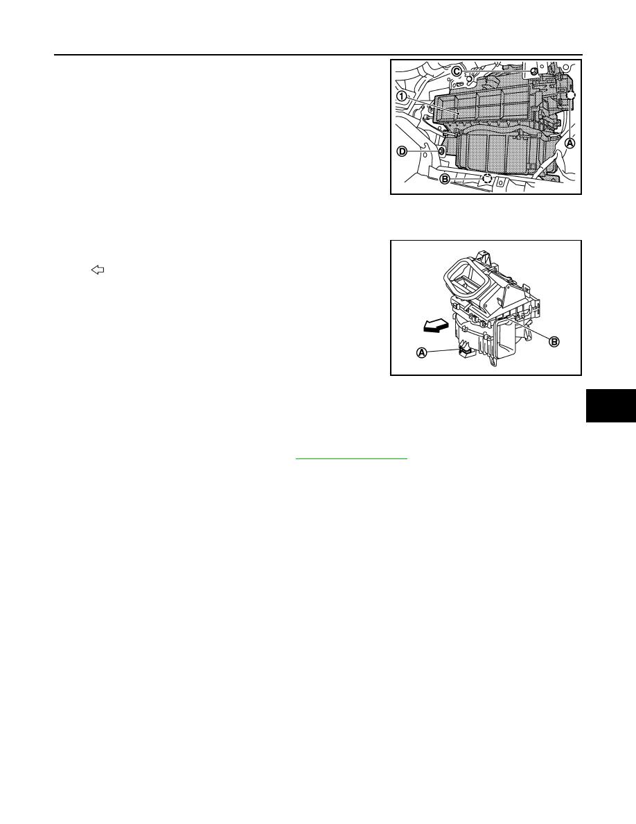
7.
Disconnect intake door motor connector (A).
8.
Disconnect the blower motor connector (B).
9.
Remove mounting bolt (C) and screw (D), from blower unit (1).
10. Remove blower unit.
CAUTION:
Move blower unit rightward, and remove locating pin (1
part) and joint. Then remove blower unit downward.
INSTALLATION
Installation is basically the reverse order of removal.
CAUTION:
Make sure locating pin (A) and joint (B) are securely inserted.
BLOWER MOTOR
BLOWER MOTOR : Removal and Installation
INFOID:0000000009160153
REMOVAL
1.
Remove instrument lower cover RH. Refer to
2.
Disconnect the blower motor connector.
3.
Remove mounting screws, and then remove the blower motor.
INSTALLATION
Installation is basically the reverse order of removal.
JSIIA1197ZZ
: Vehicle front
JSIIA1198ZZ
2014 GT-R
WCS
WCS-1
DRIVER INFORMATION & MULTIMEDIA
C
D
E
F
G
H
I
J
K
L
M
B
SECTION
WCS
A
O
P
CONTENTS
WARNING CHIME SYSTEM
SYSTEM DESCRIPTION . . . . . . . ..
WARNING CHIME SYSTEM . . . . . . . ...
WARNING CHIME SYSTEM . . . . . . . . . ...
WARNING CHIME SYSTEM : System Diagram . ...
WARNING CHIME SYSTEM : System Description
. ..
WARNING CHIME SYSTEM : Component Parts
Location . . . . . . . . . . . . . . . . .....
WARNING CHIME SYSTEM : Component De-
scription . . . . . . . . . . . . . . . . .....
LIGHT REMINDER WARNING CHIME . . . . . ...
LIGHT REMINDER WARNING CHIME : System
Diagram . . . . . . . . . . . . . . . . .....
LIGHT REMINDER WARNING CHIME : System
Description . . . . . . . . . . . . . . . ....
LIGHT REMINDER WARNING CHIME : Compo-
nent Parts Location . . . . . . . . . . . . ...
LIGHT REMINDER WARNING CHIME : Compo-
nent Description . . . . . . . . . . . . . ....
SEAT BELT WARNING CHIME . . . . . . . . ..
SEAT BELT WARNING CHIME : System Diagram
. ..
SEAT BELT WARNING CHIME : System Descrip-
tion . . . . . . . . . . . . . . . . . . ....
SEAT BELT WARNING CHIME : Component
Parts Location . . . . . . . . . . . . . . ...
SEAT BELT WARNING CHIME : Component De-
scription . . . . . . . . . . . . . . . . .....
PARKING BRAKE RELEASE WARNING CHIME . ..
PARKING BRAKE RELEASE WARNING CHIME
: System Diagram . . . . . . . . . . . . . ..
PARKING BRAKE RELEASE WARNING CHIME
: System Description . . . . . . . . . . . .....
PARKING BRAKE RELEASE WARNING CHIME
: Component Parts Location . . . . . . . . .
PARKING BRAKE RELEASE WARNING CHIME
: Component Description . . . . . . . . . . .
REVERSE WARNING CHIME . . . . . . . . ...
REVERSE WARNING CHIME : System Diagram .
REVERSE WARNING CHIME : System Descrip-
tion . . . . . . . . . . . . . . . . . . ...
REVERSE WARNING CHIME : Component Parts
Location . . . . . . . . . . . . . . . . ...
REVERSE WARNING CHIME : Component De-
scription . . . . . . . . . . . . . . . . ...
DTC/CIRCUIT DIAGNOSIS . . . . . . .
POWER SUPPLY AND GROUND CIRCUIT .
COMBINATION METER . . . . . . . . . . .
COMBINATION METER : Diagnosis Procedure . .
BCM (BODY CONTROL MODULE) . . . . . . ..
BCM (BODY CONTROL MODULE) : Diagnosis
Procedure . . . . . . . . . . . . . . . .
METER BUZZER CIRCUIT . . . . . . . ...
Description . . . . . . . . . . . . . . . ...
Diagnosis Procedure . . . . . . . . . . . ..
SEAT BELT BUCKLE SWITCH SIGNAL CIR-
CUIT . . . . . . . . . . . . . . . . ..
Description . . . . . . . . . . . . . . . ...
Diagnosis Procedure . . . . . . . . . . . ..
Component Inspection . . . . . . . . . . . .
WARNING CHIME SYSTEM . . . . . . . .
Wiring Diagram - WARNING CHIME - . . . . .
ECU DIAGNOSIS INFORMATION . . . ..
COMBINATION METER . . . . . . . . ...
Reference Value . . . . . . . . . . . . . ..
Wiring Diagram - METER - . . . . . . . . . ..
Fail-safe . . . . . . . . . . . . . . . . ...
BCM (BODY CONTROL MODULE) . . . . .
Wiring Diagram - BCM - . . . . . . . . . . ..
2014 GT-R
WCS-2
SYMPTOM DIAGNOSIS . . . . . . . .
Description . . . . . . . . . . . . . . . ..
Diagnosis Procedure . . . . . . . . . . . ..
THE LIGHT REMINDER WARNING DOES
NOT SOUND . . . . . . . . . . . . . ..
Description . . . . . . . . . . . . . . . ..
Diagnosis Procedure . . . . . . . . . . . ..
THE SEAT BELT WARNING CONTINUES
SOUNDING, OR DOES NOT SOUND . . . ...
Description . . . . . . . . . . . . . . . ..
Trouble diagnosis procedure . . . . . . . . ..
PRECAUTION . . . . . . . . . . .
PRECAUTIONS . . . . . . . . . . . . .
Precaution for Working Range at a Regular Deal-
ership . . . . . . . . . . . . . . . . . ..
Precaution for Battery Service . . . . . . . .
2014 GT-R

WCS
WARNING CHIME SYSTEM
WCS-3
< SYSTEM DESCRIPTION >
C
D
E
F
G
H
I
J
K
L
M
B
A
O
P
SYSTEM DESCRIPTION
WARNING CHIME SYSTEM
WARNING CHIME SYSTEM
WARNING CHIME SYSTEM : System Diagram
INFOID:0000000009188766
WARNING CHIME SYSTEM : System Description
INFOID:0000000009188767
COMBINATION METER
• The buzzer (1) for the warning chime system is integrated in the
combination meter.
• The combination meter sounds the alarm buzzer installed in the
combination meter when receiving the signal from various units
and switches.
BCM
BCM receives signals from various units and switches, and transmits the buzzer output signal to the combina-
tion meter via CAN communication if it judges that the warning buzzer should be activated.
BCM warning function list
NNNIA0183GB
NNNIA0016ZZ
Warning functions
Signal name
Light reminder warning chime
• Position light request signal
• Door switch signal (driver side)
Seat belt warning chime
Seat belt buckle switch signal (driver side)
Reverse warning chime (For Canada)
Shift position signal
2014 GT-R
WCS-4
< SYSTEM DESCRIPTION >
WARNING CHIME SYSTEM
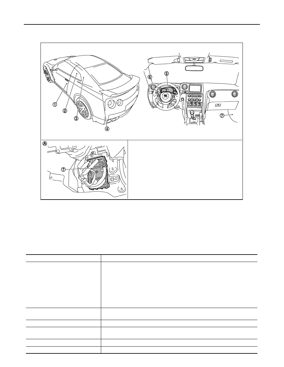
WARNING CHIME SYSTEM : Component Parts Location
INFOID:0000000009188768
WARNING CHIME SYSTEM : Component Description
INFOID:0000000009188769
1.
Door switch (driver side)
2.
Seat belt buckle switch (driver side)
3.
Parking brake switch
4.
TCM
5.
Combination meter
6.
Combination switch (lighting switch)
7.
BCM
A.
Lower part of passenger side dash-
board
NNNIA0184ZZ
Unit
Description
Combination meter
• Receives the buzzer output signal from BCM via the CAN communication and sounds
the buzzer.
• Judges that the parking brake is still applied according to the vehicle speed signal re-
ceived from the ABS actuator and electric unit (control unit) via CAN communication
and the parking brake switch signal from the parking brake switch and sounds the
warning buzzer.
• Receives the vehicle speed signal from the ABS actuator and electric unit (control unit)
and the seat belt buckle switch signal (driver side) from the seat belt buckle switch (driv-
er side) and transmits them to BCM via CAN communication.
BCM
Based on the signals received from various units and switches, transmits the buzzer out-
put signal to the combination meter via CAN communication.
TCM
Transmits the shift position signal to the BCM via CAN communication.
ABS actuator and electric unit (control
unit)
Transmits the vehicle speed signal to the combination meter via CAN communication.
Seat belt buckle switch (driver side)
Transmits the seat belt buckle switch signal (driver side) to the combination meter.
Combination switch (lighting switch)
Transmits the position light request signal to BCM.
2014 GT-R

WCS
WARNING CHIME SYSTEM
WCS-5
< SYSTEM DESCRIPTION >
C
D
E
F
G
H
I
J
K
L
M
B
A
O
P
LIGHT REMINDER WARNING CHIME
LIGHT REMINDER WARNING CHIME : System Diagram
INFOID:0000000009188770
LIGHT REMINDER WARNING CHIME : System Description
INFOID:0000000009188771
DESCRIPTION
With ignition switch in the OFF or ACC position, when the driver door is open and the lighting switch is the 1st
or 2nd position, the light warning chime will sound.
• BCM detects ignition switch in the OFF or ACC position, door switch (driver side) ON, and lighting switch in
1st or 2nd position. Then the BCM transmits the buzzer output signal (light reminder warning chime) to com-
bination meter with CAN communication line.
• When combination meter receives buzzer output signal (light reminder warning chime), it sounds the buzzer.
WARNING OPERATION CONDITIONS
If all of the following conditions are fulfilled.
• Ignition switch is in the OFF or ACC
• Lighting switch is in the 1st or 2nd position
• Door switch (driver side) is ON
WARNING CANCEL CONDITIONS
Warning is canceled if any of the following conditions is fulfilled.
• Lighting switch OFF
• Ignition switch ON
• Door switch (driver side) is OFF
Door switch (driver side)
Transmits the door switch signal (driver side) to BCM.
Parking brake switch
Transmits the parking brake switch signal to the combination meter.
Unit
Description
JPNIA1151GB
2014 GT-R

WCS-6
< SYSTEM DESCRIPTION >
WARNING CHIME SYSTEM
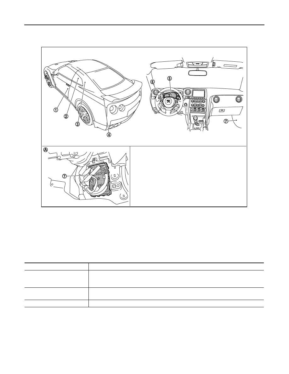
LIGHT REMINDER WARNING CHIME : Component Parts Location
INFOID:0000000009188772
LIGHT REMINDER WARNING CHIME : Component Description
INFOID:0000000009188773
SEAT BELT WARNING CHIME
1.
Door switch (driver side)
2.
Seat belt buckle switch (driver side)
3.
Parking brake switch
4.
TCM
5.
Combination meter
6.
Combination switch (lighting switch)
7.
BCM
A.
Lower part of passenger side dash-
board
NNNIA0184ZZ
Unit
Description
Combination meter
Receives a buzzer output signal from the BCM and sounds the buzzer.
BCM
Judges the light warning conditions from the signals provided by various switches and transmits a
buzzer output signal to the combination meter via CAN communication line if necessary.
Combination switch
(Lighting switch)
Transmits the position light request signal to BCM.
Door switch (driver side)
Transmits the door switch signal (driver side) to BCM.
2014 GT-R

WCS
WARNING CHIME SYSTEM
WCS-7
< SYSTEM DESCRIPTION >
C
D
E
F
G
H
I
J
K
L
M
B
A
O
P
SEAT BELT WARNING CHIME : System Diagram
INFOID:0000000009188774
SEAT BELT WARNING CHIME : System Description
INFOID:0000000009188775
DESCRIPTION
With ignition switch turned ON and driver seat belt unfastened, seat belt warning chime will sound for approxi-
mately 6 seconds.
• The combination meter receives the seat belt buckle switch signal from seat belt buckle switch (driver side)
and transmits it to the BCM via CAN communication.
• The BCM receives seat belt buckle switch signal from combination meter via CAN communication.
• The BCM detects seat belt reminder warning based on the received signal and transmits the buzzer output
signal to combination meter via CAN communication.
• The combination meter receives the buzzer output signal from BCM via CAN communication and sounds the
warning buzzer.
WARNING OPERATION CONDITIONS
If all of the following conditions are fulfilled, the warning buzzer will sound.
• Ignition switch OFF
→
ON
• Seat belt buckle switch (driver side) is ON (driver seat belt not fastened)
WARNING CANCEL CONDITIONS
Warning is canceled if any of the following conditions are fulfilled.
• Ignition switch OFF
• Seat belt buckle switch (driver side) is OFF (driver seat belt fastened)
JPNIA1152GB
2014 GT-R

WCS-8
< SYSTEM DESCRIPTION >
WARNING CHIME SYSTEM
SEAT BELT WARNING CHIME : Component Parts Location
INFOID:0000000009188776
SEAT BELT WARNING CHIME : Component Description
INFOID:0000000009188777
PARKING BRAKE RELEASE WARNING CHIME
1.
Door switch (driver side)
2.
Seat belt buckle switch (driver side)
3.
Parking brake switch
4.
TCM
5.
Combination meter
6.
Combination switch (lighting switch)
7.
BCM
A.
Lower part of passenger side dash-
board
NNNIA0184ZZ
Unit
Description
Combination meter
• Receives the seat belt buckle switch signal from the seat belt buckle switch and transmits it to
BCM via CAN communication line.
• Receives a buzzer output signal from the BCM and sounds the buzzer.
BCM
Judges the seat belt warning condition according to the seat belt buckle switch signal received from
the combination meter via CAN communication and transmits a buzzer output signal to the combi-
nation meter via CAN communication line if necessary.
Seat belt buckle switch
(driver side)
Transmits the seat belt buckle switch signal to the combination meter.
2014 GT-R

WCS
WARNING CHIME SYSTEM
WCS-9
< SYSTEM DESCRIPTION >
C
D
E
F
G
H
I
J
K
L
M
B
A
O
P
PARKING BRAKE RELEASE WARNING CHIME : System Diagram
INFOID:0000000009188778
PARKING BRAKE RELEASE WARNING CHIME : System Description
INFOID:0000000009188779
DESCRIPTION
Parking brake release warning chime judges the remaining parking brake according to the vehicle speed sig-
nal received from the ABS actuator and electric unit (control unit) via CAN communication and the parking
brake switch signal from parking brake switch to sound the warning buzzer.
WARNING OPERATION CONDITIONS
If all of the following conditions are fulfilled.
• Vehicle speed is 7 km/h (4.3 MPH) or higher
• Parking brake switch ON
WARNING CANCEL CONDITIONS
Warning is canceled if any of the following conditions are fulfilled.
• Vehicle speed is approximately 3 km/h (1.9 MPH) or less
• Parking brake switch OFF
JPNIA0751GB
2014 GT-R
WCS-10
< SYSTEM DESCRIPTION >
WARNING CHIME SYSTEM
PARKING BRAKE RELEASE WARNING CHIME : Component Parts Location
INFOID:0000000009188780
PARKING BRAKE RELEASE WARNING CHIME : Component Description
INFOID:0000000009188781
REVERSE WARNING CHIME
1.
Door switch (driver side)
2.
Seat belt buckle switch (driver side)
3.
Parking brake switch
4.
TCM
5.
Combination meter
6.
Combination switch (lighting switch)
7.
BCM
A.
Lower part of passenger side dash-
board
NNNIA0184ZZ
Unit
Description
Combination meter
Judges the remaining parking brake according to the vehicle speed signal received from the ABS
actuator and electric unit (control unit) via CAN communication and the parking brake switch signal
from parking brake switch and sounds the warning buzzer.
ABS actuator and electric unit
(control unit)
Transmits the vehicle speed signal to the combination meter via CAN communication.
Parking brake switch
Transmits the parking brake switch signal to the combination meter.
2014 GT-R

WCS
WARNING CHIME SYSTEM
WCS-11
< SYSTEM DESCRIPTION >
C
D
E
F
G
H
I
J
K
L
M
B
A
O
P
REVERSE WARNING CHIME : System Diagram
INFOID:0000000009188782
REVERSE WARNING CHIME : System Description
INFOID:0000000009188783
DESCRIPTION
• The BCM receives shift position signal (reverse range) from TCM via CAN communication.
• The BCM detects reverse warning chime based on the received signal and transmits the buzzer output sig-
nal to combination meter via CAN communication.
• The combination meter receives the buzzer output signal from BCM via CAN communication and sounds the
warning buzzer.
REVERSE WARNING CHIME : Component Parts Location
INFOID:0000000009188784
NNNIA0185GB
1.
Door switch (driver side)
2.
Seat belt buckle switch (driver side)
3.
Parking brake switch
4.
TCM
5.
Combination meter
6.
Combination switch (lighting switch)
7.
BCM
A.
Lower part of passenger side dash-
board
NNNIA0184ZZ
2014 GT-R

WCS-12
< SYSTEM DESCRIPTION >
WARNING CHIME SYSTEM
REVERSE WARNING CHIME : Component Description
INFOID:0000000009188785
Unit
Description
Combination meter
Receives a buzzer output signal from the BCM and sounds the buzzer.
BCM
• The BCM receives shift position signal from TCM via CAN communication.
• The BCM detects reverse warning based on the received signal and transmits the buzzer output
signal to combination meter via CAN communication.
TCM
Transmits the shift position signal to BCM via CAN communication.
2014 GT-R

WCS
POWER SUPPLY AND GROUND CIRCUIT
WCS-13
< DTC/CIRCUIT DIAGNOSIS >
C
D
E
F
G
H
I
J
K
L
M
B
A
O
P
DTC/CIRCUIT DIAGNOSIS
POWER SUPPLY AND GROUND CIRCUIT
COMBINATION METER
COMBINATION METER : Diagnosis Procedure
INFOID:0000000009188786
1.
CHECK FUSES
Check that the following fuses are not blown:
Is the inspection result normal?
YES
>> GO TO 2.
NO
>> Replace the fuse with a new one after repairing the applicable circuit.
2.
CHECK POWER SUPPLY CIRCUIT
Check the voltage between the combination meter harness connector terminals and the ground.
Is the inspection result normal?
YES
>> GO TO 3.
NO
>> Repair the harness between the fuse and the combination meter.
3.
CHECK GROUND CIRCUIT
1.
Turn the ignition switch OFF.
2.
Disconnect the combination meter connector.
3.
Check for continuity between the combination meter harness connector terminals and the ground.
Is the inspection result normal?
YES
>> INSPECTION END
NO
>> Repair the harnesses or connectors.
BCM (BODY CONTROL MODULE)
BCM (BODY CONTROL MODULE) : Diagnosis Procedure
INFOID:0000000009188787
1.
CHECK FUSE AND FUSIBLE LINK
Check that the following fuse and fusible link are not blown.
Is the fuse fusing?
YES
>> Replace the blown fuse or fusible link after repairing the affected circuit if a fuse or fusible link is
blown.
Power source
Fuse No.
Battery
11
Ignition switch ON or START
4
Terminal No.
Signal name
Ignition switch
Voltage
1
Battery power supply
OFF
Battery voltage
2
Ignition signal
ON
Battery voltage
Combination meter
Ground
Continuity
Connector
Terminal
M53
3
Existed
5
Signal name
Fuse and fusible link No.
Battery power supply
I
10
2014 GT-R

WCS-14
< DTC/CIRCUIT DIAGNOSIS >
POWER SUPPLY AND GROUND CIRCUIT
NO
>> GO TO 2.
2.
CHECK POWER SUPPLY CIRCUIT
1.
Turn ignition switch OFF.
2.
Disconnect BCM connectors.
3.
Check voltage between BCM harness connector and ground.
Is the measurement value normal?
YES
>> GO TO 3.
NO
>> Repair harness or connector.
3.
CHECK GROUND CIRCUIT
Check continuity between BCM harness connector and ground.
Does continuity exist?
YES
>> INSPECTION END
NO
>> Repair harness or connector.
Terminals
Voltage
(Approx.)
(+)
(
−
)
BCM
Ground
Connector
Terminal
M118
1
Battery voltage
M119
11
BCM
Ground
Continuity
Connector
Terminal
M119
13
Existed
2014 GT-R

WCS
METER BUZZER CIRCUIT
WCS-15
< DTC/CIRCUIT DIAGNOSIS >
C
D
E
F
G
H
I
J
K
L
M
B
A
O
P
METER BUZZER CIRCUIT
Description
INFOID:0000000009188788
• The buzzer for warning chime system is installed in the combination meter.
• The combination meter sounds the alarm buzzer based on the signals transmitted from various units and
switches.
Diagnosis Procedure
INFOID:0000000009188789
1.
CHECK POWER SUPPLY OF COMBINATION METER
Check power supply of combination meter. Refer to
MWI-40, "COMBINATION METER : Diagnosis Proce-
.
Is the inspection result normal?
YES
>> INSPECTION END
NO
>> Repair power supply circuit of combination meter. Refer to
2014 GT-R
Нет комментариевНе стесняйтесь поделиться с нами вашим ценным мнением.
Текст