Qashqai J11. Body repair — part 20
BODY ALIGNMENT
BRM-305
< SERVICE DATA AND SPECIFICATIONS (SDS)
[FOR RUSSIA]
C
D
E
F
G
H
I
J
L
M
A
B
BRM
N
O
P
«The others»
Unit: mm (in)
MEASUREMENT POINTS
Unit: mm (in)
JSKIA3911GB
Point
Dimension
Memo
Point
Dimension
Memo
Point
Dimension
Memo
-
1280 (50.39)
-
1486 (58.50)*
-
850 (33.46)*
-
1701 (66.97)*
-
1660 (65.35)*
-
493 (19.41)*
-
1431 (56.34)*
-
1462 (57.56)
-
1013 (39.88)*
-
1604 (63.15)*
-
1705 (67.13)*
-
480 (18.90)*
-
1462 (57.56)
-
1533 (60.35)*
-
1609 (63.35)
-
1841 (72.48)*
-
1279 (50.35)
-
1152 (45.35)*
-
1614 (63.54)*
-
1637 (64.45)*
-
1157 (45.55)*
-
1374 (54.09)
-
1461 (57.52)
-
1636 (64.41)
-
1562 (61.50)*
-
1139 (44.84)*
-
1215 (47.83)*
-
1461 (57.52)
-
790 (31.10)*
-
1094 (43.07)*
-
1369 (53.90)
-
1190 (46.85)*
-
1618 (63.70)
-
1553 (61.14)*
-
833 (32.80)*
-
1633 (64.29)
BRM-306
< SERVICE DATA AND SPECIFICATIONS (SDS)
[FOR RUSSIA]
BODY ALIGNMENT
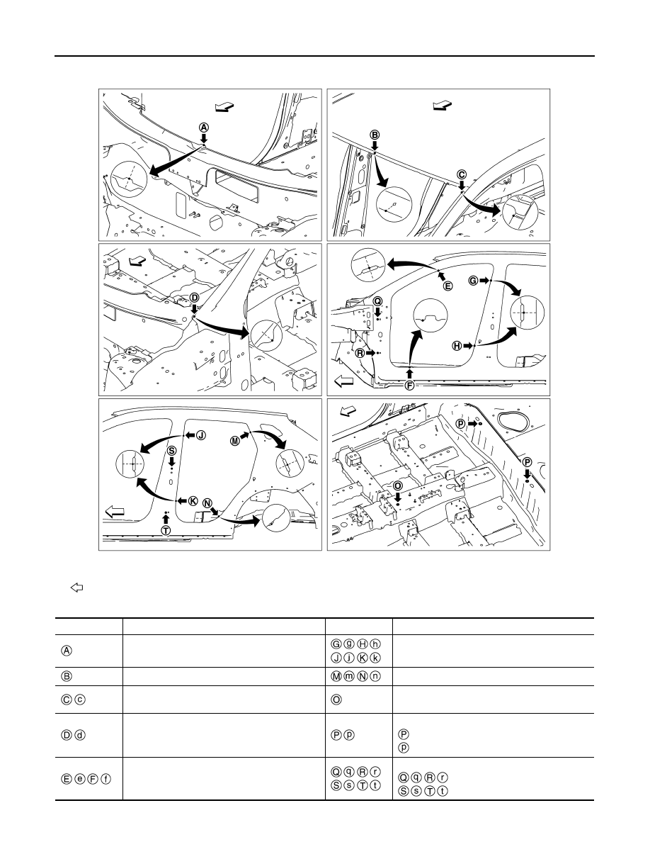
Unit: mm (in)
: Vehicle front
JSKIA3926ZZ
Point
Material
Point
Material
Cowl top positioning mark of center positioning
mark
Center pillar indent
Roof flange end of center positioning mark
Rear fender indent
Outer side body joggle
Trans control reinforcement hole center of center
positioning mark 12
×
14 (0.47
×
0.55)
Outer side body indent
Rear seat crossmember hole center
:
φ
16 (0.63)
: 18
×
16 (0.71
×
0.63)
Front pillar indent
Door hinge installing hole center
:
φ
12 (0.47)
:
φ
9 (0.35)
BODY ALIGNMENT
BRM-307
< SERVICE DATA AND SPECIFICATIONS (SDS)
[FOR RUSSIA]
C
D
E
F
G
H
I
J
L
M
A
B
BRM
N
O
P
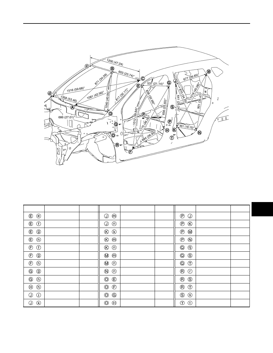
Passenger Compartment (With sunroof models)
INFOID:0000000010499731
MEASUREMENT
Dimensions marked with
″
*
″
indicate symmetrically identical dimensions on both the right and left hand of the
vehicle.
«The others»
Unit: mm (in)
Unit: mm (in)
JSKIA3913GB
Point
Dimension
Memo
Point
Dimension
Memo
Point
Dimension
Memo
-
1280 (50.39)
-
1486 (58.50)*
-
850 (33.46)*
-
1701 (66.97)*
-
1660 (65.35)*
-
493 (19.41)*
-
1431 (56.34)*
-
1462 (57.56)
-
1013 (39.88)*
-
1604 (63.15)*
-
1705 (67.13)*
-
480 (18.90)*
-
1462 (57.56)
-
1533 (60.35)*
-
1609 (63.35)
-
1841 (72.48)*
-
1279 (50.35)
-
1152 (45.35)*
-
1614 (63.54)*
-
1637 (64.45)*
-
1157 (45.55)*
-
1374 (54.09)
-
1461 (57.52)
-
1636 (64.41)
-
1562 (61.50)*
-
1139 (44.84)*
-
1215 (47.83)*
-
1461 (57.52)
-
790 (31.10)*
-
1094 (43.07)*
-
1369 (53.90)
-
1190 (46.85)*
-
1618 (63.70)
-
1553 (61.14)*
-
833 (32.80)*
-
1633 (64.29)
B R M - 3 0 8
< SERVICE DATA AND SPECIFICATIONS (SDS)
[FOR RUSSIA]
BODY ALIGNMENT
MEASUREMENT POINTS
Unit: mm (in)
: Vehicle front
JSKIA3928ZZ
Point
Material
Point
Material
Cowl top positioning mark of center positioning
mark
Center pillar indent
Upper front roof rail flange end of center position-
ing mark
Rear fender indent
Outer side body joggle
Trans control reinforcement hole center of center
positioning mark 12
×
14 (0.47
×
0.55)
BODY ALIGNMENT
BRM-309
< SERVICE DATA AND SPECIFICATIONS (SDS)
[FOR RUSSIA]
C
D
E
F
G
H
I
J
L
M
A
B
BRM
N
O
P
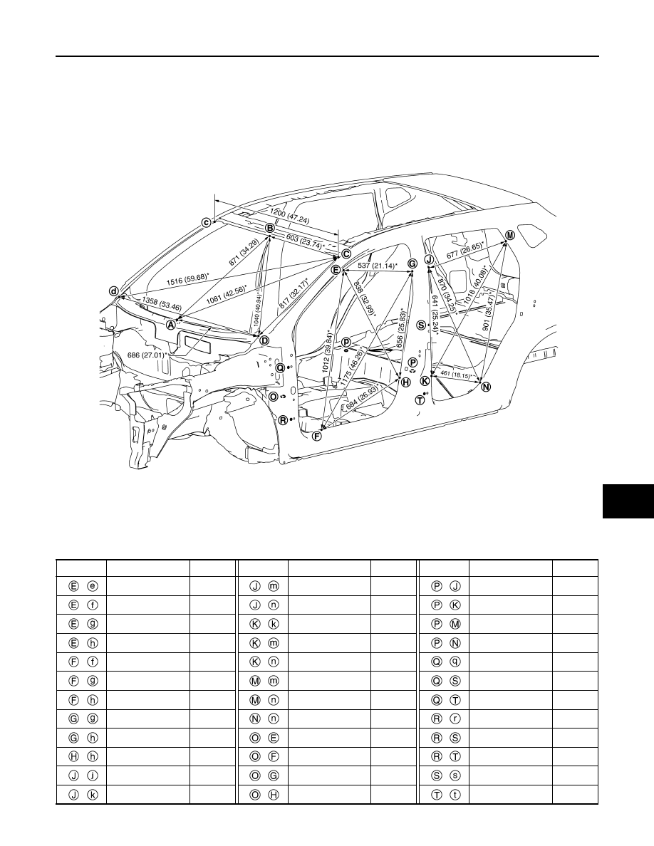
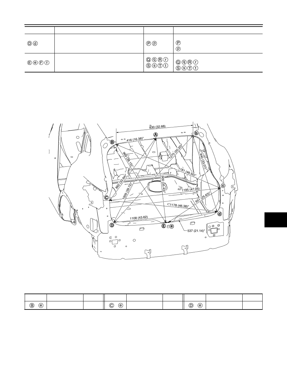
Rear Body
INFOID:0000000010499732
MEASUREMENT
Dimensions marked with
″
*
″
indicate symmetrically identical dimensions on both the right and left hand of the
vehicle.
«The others»
Unit: mm (in)
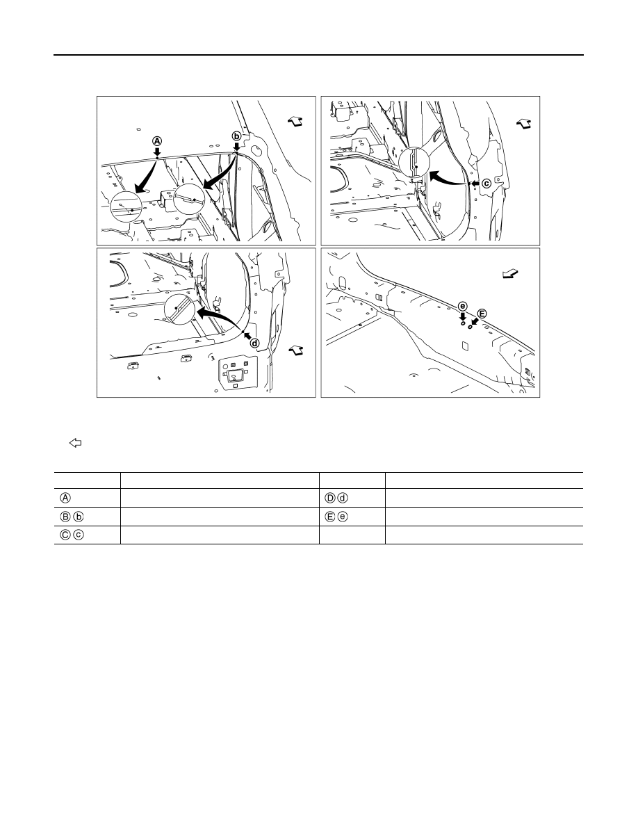
MEASUREMENT POINTS
Outer side body indent
Rear seat crossmember hole center
:
φ
16 (0.63)
: 18
×
16 (0.71
×
0.63)
Front pillar indent
Door hinge installing hole center
:
φ
12 (0.47)
:
φ
9 (0.35)
Point
Material
Point
Material
Unit: mm (in)
JSKIA3915GB
Point
Dimension
Memo
Point
Dimension
Memo
Point
Dimension
Memo
–
987 (38.86)*
–
688 (27.09)*
–
578 (22.76)*
BRM-310
< SERVICE DATA AND SPECIFICATIONS (SDS)
[FOR RUSSIA]
BODY ALIGNMENT
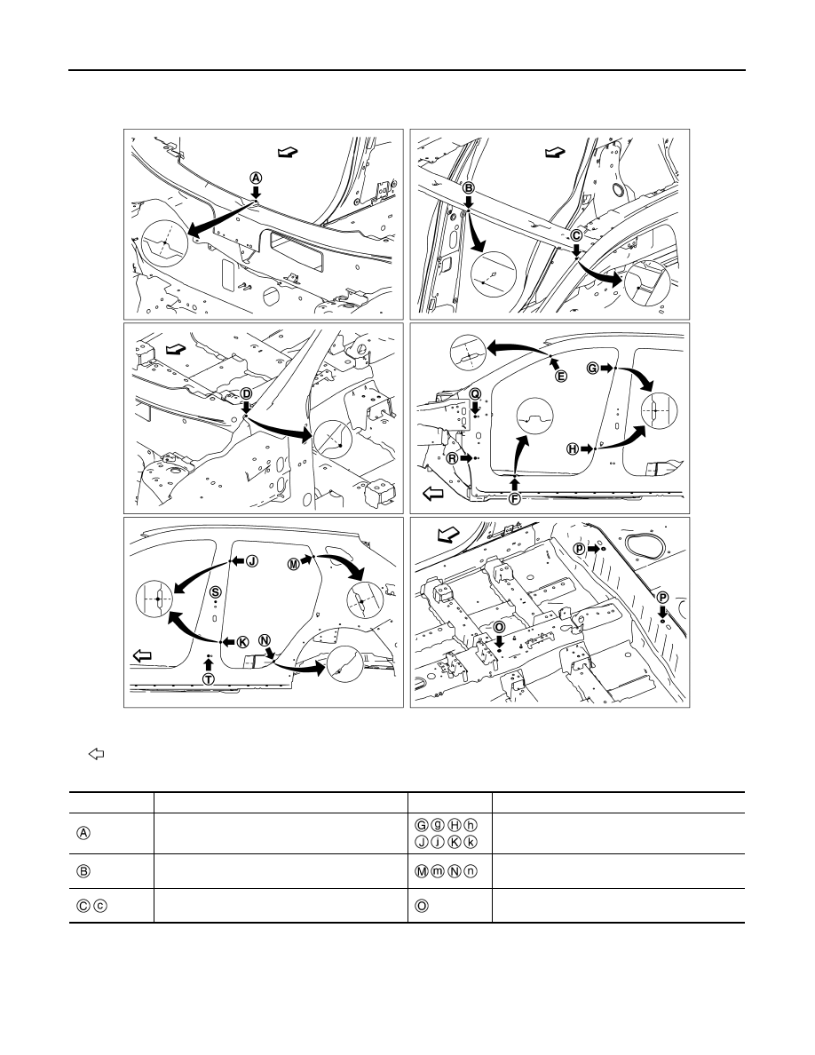
Unit: mm (in)
: Vehicle front
JSKIA3916ZZ
Point
Material
Point
Material
Roof flange end of center positioning mark
Lower rear pillar reinforcement joggle
Rear fender extension joggle
Back door lock support hole center
φ
14 (0.55)
Lower back pillar main joggle

LOCATION OF PLASTIC PARTS
BRM-311
< SERVICE DATA AND SPECIFICATIONS (SDS)
[FOR RUSSIA]
C
D
E
F
G
H
I
J
L
M
A
B
BRM
N
O
P
LOCATION OF PLASTIC PARTS
Precautions for Plastics
INFOID:0000000010499733
CAUTION:
• When repairing and painting a portion of the body adjacent to plastic parts, consider their characteristics (influence of heat
and solvent) and remove them if necessary or take suitable measures to protect them.
• Plastic parts should be repaired and painted using methods suiting the materials
,
characteristics.
Abbre-
viation
Material name
Heat resisting
temperature
°
C (
°
F)
Resistance to gasoline and
solvents
Other cautions
PE
Polyethylene
60 (140)
Gasoline and most solvents are
harmless if applied for a very
short time (wipe out quickly).
Flammable
ABS
Acrylonitrile Butadiene Styrene
80 (176)
Avoid gasoline and solvents.
—
AES
Acrylonitrile Ethylene Styrene
80 (176)
↑
—
EPM/
EPDM
Ethylene Propylene (Diene) co-
polymer
80 (176)
Gasoline and most solvents are
harmless if applied for a very
short time (wipe out quickly).
Flammable
PS
Polystyrene
80 (176)
Avoid solvents.
Flammable
PVC
Poly Vinyl Chloride
80 (176)
Gasoline and most solvents are
harmless if applied for a very
short time (wipe out quickly).
Poisonous gas is emitted
when burned.
TPO
Thermoplastic Olefine
80 (176)
↑
Flammable
AAS
Acrylonitrile Acrylic Styrene
85 (185)
Avoid gasoline and solvents.
—
PMMA
Poly Methyl Methacrylate
85 (185)
↑
—
EVAC
Ethylene Vinyl Acetate
90 (194)
↑
—
PP
Polypropylene
90 (194)
Gasoline and most solvents are
harmless if applied for a very
short time (wipe out quickly).
Flammable, avoid bat-
tery acid.
PUR
Polyurethane
90 (194)
Avoid gasoline and solvents.
—
UP
Unsaturated Polyester
90 (194)
↑
Flammable
ASA
Acrylonitrile Styrene Acrylate
100 (212)
↑
Flammable
PPE
Poly Phenylene Ether
110 (230)
↑
—
TPU
Thermoplastic Urethane
110 (230)
↑
—
PBT+
PC
Poly Butylene Terephthalate +
Polycarbonate
120 (248)
↑
Flammable
PC
Polycarbonate
120 (248)
↑
—
POM
Poly Oxymethylene
120 (248)
↑
Avoid battery acid.
PA
Polyamide
140 (284)
↑
Avoid immersing in wa-
ter.
PBT
Poly Butylene Terephthalate
140 (284)
↑
—
PAR
Polyarylate
180 (356)
↑
—
PET
Polyethylene terephthalate
180 (356)
↑
—
PEI
Polyetherimide
200 (392)
↑
—
BRM-312
< SERVICE DATA AND SPECIFICATIONS (SDS)
[FOR RUSSIA]
LOCATION OF PLASTIC PARTS
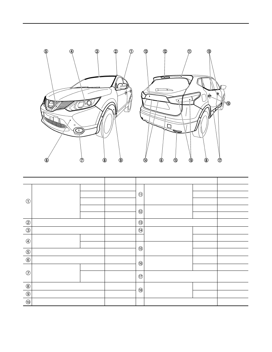
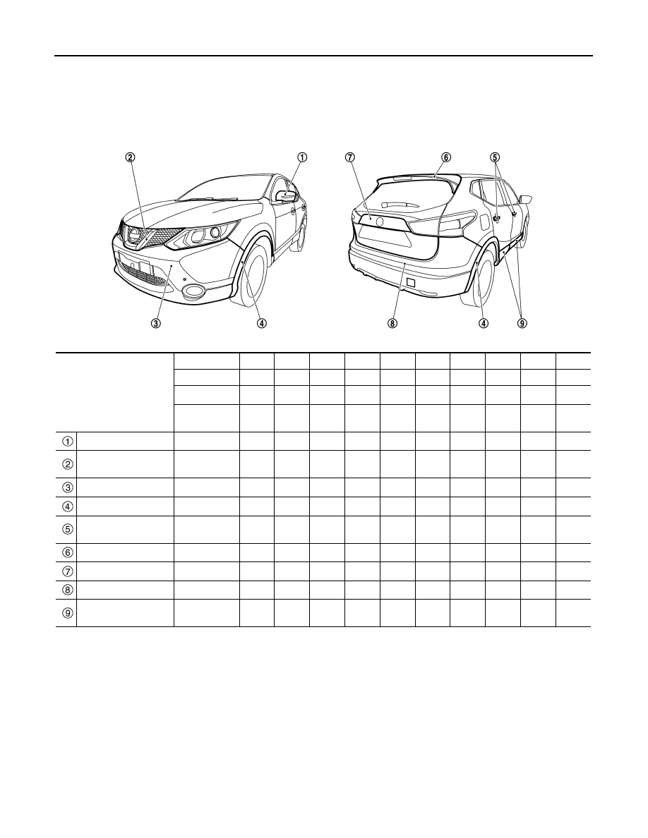
Location of Plastic Parts
INFOID:0000000010499734
Component
Material
Component
Material
Door mirror
Case
ASA
Rear spoiler
Upper
PC + PET
Lower case
ASA
Lower
ASA
Base
Aluminum
Side
PMMA
Base cover
ASA
High mount stop lamp
Lens
PMMA
Cover
ABS
Housing
ABS
Side roof molding
PVC + Stainless
Back door finisher
ABS
Wind shield molding
PVC
License plate lamp
Lens
PC
Front combination lamp
Lens
PC
Housing
PC
Housing
PP
Reflex reflector
Lens
PMMA
Front grille
ABS
Housing
ABS
Bumper fascia
PP + EPM
Rear combination lamp
Lens
PMMA
Front fog lamp
Lens
Glass
Housing
ABS
Housing
PBT + ASA +
Glass fiber
Door outside lower molding
PP + EPDM
Fillet molding
PP + EPDM
Door outside handle
Grip body
PA + Glass fiber
Front fender protector
PP
Grip cover
PA + Glass fiber
Door outside molding
PVC + Stainless
JSKIA3931ZZ
LOCATION OF PLASTIC PARTS
BRM-313
< SERVICE DATA AND SPECIFICATIONS (SDS)
[FOR RUSSIA]
C
D
E
F
G
H
I
J
L
M
A
B
BRM
N
O
P
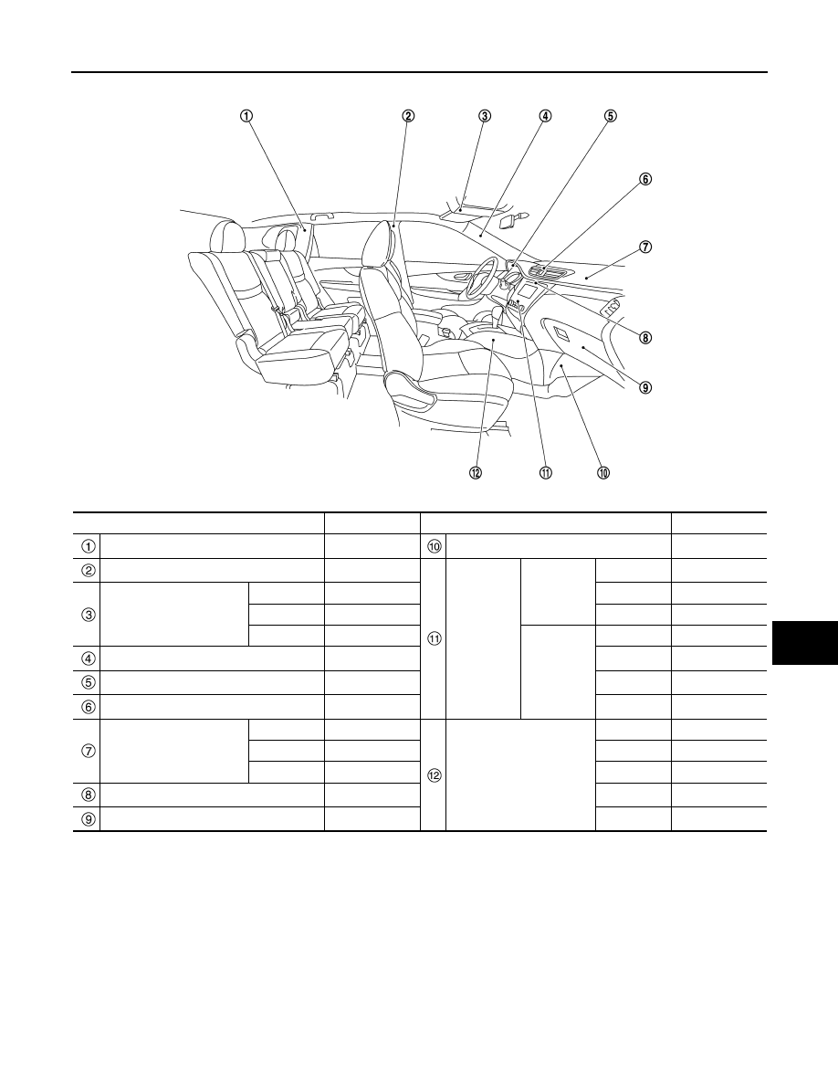
Component
Material
Component
Material
Rear pillar finisher
PP
Instrument lower cover
PP + EPDM
Center pillar garnish
PP
A/C Control
Manual A/C
Finisher
PC + ABS
Map lamp
Lens
PC
Switch
PC
Housing
PP
Case
ABS
Finisher
PP
Auto A/C
Finisher
PC + ABS
Front pillar garnish
PP
Switch
PC
Cluster lid A
PP
Case
PC + ABS
Center ventilator finisher
PC + ABS
Lens
PC
Instrument panel
Skin
TPO
Center console
Body
PP + EPDM
Pad
PUR
Console box
PP
Core
PP + EPDM
Inner lid
PP + EPDM
Cluster lid C
PC + ABS
Insert lid
PC + ABS
Glove box
PP
Cup holder
PP + EPDM
JSKIA3932ZZ
BRM-314
< VEHICLE INFORMATION >
[EXCEPT FOR EUROPE AND RUSSIA (LHD)]
BODY EXTERIOR PAINT COLOR
VEHICLE INFORMATION
BODY EXTERIOR PAINT COLOR
Body Exterior Paint Color
INFOID:0000000010499108
NOTE:
• S: 1-Coat solid
• 2M: 2-Coat Metallic
• 2S: 2-Coat solid
• 3P: 3-Coat pearl
• 2PM: 2-Coat Pearl metallic
Component
Color code
B326
BZ11
BKY0
BGAB
BKAD
BNAJ
BCAP
BRBN
BZ10
BQAB
Description
White
Black
Silver
Black
Gray
Red
Brown
Blue
Red
White
Paint type
note
S
2M
2M
2M
2M
2PM
2M
2M
2S
3P
Standard
clear coat
–
×
×
×
×
×
×
×
×
×
Door mirror cover
Body color
B326
BZ11
BKY0
BGAB
BKAD
BNAJ
BCAP
BRBN
BZ10
BQAB
Front grille molding
Chromium
plate
Cr
Cr
Cr
Cr
Cr
Cr
Cr
Cr
Cr
Cr
Front bumper fascia
Body color
B326
BZ11
BKY0
BGAB
BKAD
BNAJ
BCAP
BRBN
BZ10
BQAB
Fillet molding
Material color
–
–
–
–
–
–
–
–
–
–
Door outside handle
Chromium
plate
Cr
Cr
Cr
Cr
Cr
Cr
Cr
Cr
Cr
Cr
Rear spoiler
Body color
B326
BZ11
BKY0
BGAB
BKAD
BNAJ
BCAP
BRBN
BZ10
BQAB
Back door finisher
Body color
B326
BZ11
BKY0
BGAB
BKAD
BNAJ
BCAP
BRBN
BZ10
BQAB
Rear bumper fascia
Body color
B326
BZ11
BKY0
BGAB
BKAD
BNAJ
BCAP
BRBN
BZ10
BQAB
Door outside lower
molding
Material color
–
–
–
–
–
–
–
–
–
–
JSKIA3881ZZ
PRECAUTIONS
BRM-315
< PRECAUTION >
[EXCEPT FOR EUROPE AND RUSSIA (LHD)]
C
D
E
F
G
H
I
J
L
M
A
B
BRM
N
O
P
PRECAUTION
PRECAUTIONS
Precautions for Removing Battery Terminal
INFOID:0000000010503256
• With the adoption of Auto ACC function, ACC power is automatically supplied by operating the intelligent key
or remote keyless entry or by opening/closing the driver side door. In addition, ACC power is supplied even
after the ignition switch is turned to the OFF position, i.e. ACC power is supplied for a certain fixed time.
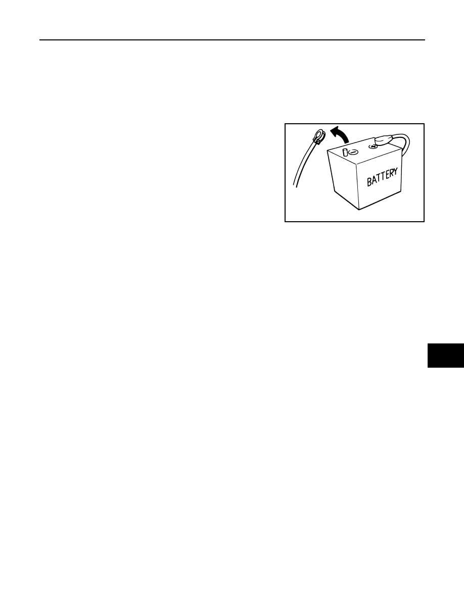
• When disconnecting the 12V battery terminal, turn off the ACC
power before disconnecting the 12V battery terminal, observing
“How to disconnect 12V battery terminal” described below.
NOTE:
Some ECUs operate for a certain fixed time even after ignition
switch is turned OFF and ignition power supply is stopped. If the
battery terminal is disconnected before ECU stops, accidental DTC
detection or ECU data damage may occur.
• For vehicles with the 2-batteries, be sure to connect the main bat-
tery and the sub battery before turning ON the ignition switch.
NOTE:
If the ignition switch is turned ON with any one of the terminals of
main battery and sub battery disconnected, then DTC may be detected.
• After installing the 12V battery, always check "Self Diagnosis Result" of all ECUs and erase DTC.
NOTE:
The removal of 12V battery may cause a DTC detection error.
HOW TO DISCONNECT 12V BATTERY TERMINAL
Disconnect 12V battery terminal according to Instruction 1 or Instruction 2 described below.
For vehicles parked by ignition switch OFF, refer to Instruction 2.
INSTRUCTION 1
1.
Open the hood.
2.
Turn key switch to the OFF position with the driver side door opened.
3.
Get out of the vehicle and close the driver side door.
4.
Wait at least 3 minutes. For vehicle with the engine listed below, remove the battery terminal after a lapse
of the specified time.
CAUTION:
While waiting, never operate the vehicle such as locking, opening, and closing doors. Violation of
this caution results in the activation of ACC power supply according to the Auto ACC function.
5.
Remove 12V battery terminal.
CAUTION:
After installing 12V battery, always check self-diagnosis results of all ECUs and erase DTC.
INSTRUCTION 2 (FOR VEHICLES PARKED BY IGNITION SWITCH OFF)
1.
Unlock the door with intelligent key or remote keyless entry.
NOTE:
At this moment, ACC power is supplied.
2.
Open the driver side door.
3.
Open the hood.
4.
Close the driver side door.
5.
Wait at least 3 minutes.
SEF289H
D4D engine
: 20 minutes
HRA2DDT
: 12 minutes
K9K engine
: 4 minutes
M9R engine
: 4 minutes
R9M engine
: 4 minutes
V9X engine
: 4 minutes
BRM-316
< PRECAUTION >
[EXCEPT FOR EUROPE AND RUSSIA (LHD)]
PRECAUTIONS
CAUTION:
While waiting, never operate the vehicle such as locking, opening, and closing doors. Violation of
this caution results in the activation of ACC power supply according to the Auto ACC function.
6.
Remove 12V battery terminal.
CAUTION:
After installing 12V battery, always check self-diagnosis results of all ECUs and erase DTC.

REPAIRING HIGH STRENGTH STEEL
BRM-317
< PRECAUTION >
[EXCEPT FOR EUROPE AND RUSSIA (LHD)]
C
D
E
F
G
H
I
J
L
M
A
B
BRM
N
O
P
REPAIRING HIGH STRENGTH STEEL
High Strength Steel (HSS)
INFOID:0000000010499109
High strength steel is used for body panels in order to reduce vehicle weight.
Accordingly, precautions in repairing automotive bodies made of high strength steel are described below:
Tensile strength
Major applicable parts
440 - 780 MPa
• Trans control reinforcement
(Center front floor assembly component part)
• 2nd crossmember
(Front floor assembly component part)
• 3rd crossmember
(Front floor assembly component part)
• 3rd crossmember reinforcement
(Front floor assembly component part)
• Lower dash crossmember
(Lower dash assembly component part)
• Side dash
(Side dash assembly component part)
• Inner front pillar reinforcement
(Side dash assembly component part)
• Front suspension spring support
(Front strut housing assembly component part)
• Engine mounting bracket reinforcement
(Front strut housing assembly component part)
• Engine mounting bracket
(Front strut housing assembly component part)
• Front bumper reinforcement assembly
• Lower front bumper stay
• Front side member closing plate (Front)
(Side member closing plate assembly component part)
• Outer add on frame bracket
(Side member closing plate assembly component part)
• Closing plate reinforcement
(Side member closing plate assembly component part)
• Front side member assembly
• Engine mounting member bracket assembly
• Front suspension mounting rear bracket assembly
• Inner sill extension
(Rear side member assembly component part)
• Inner rear sill
(Rear side member assembly component part)
• Outer rear anchor reinforcement
(Rear side member assembly component part)
• Rear side member extension assembly
• Inner front side roof rail assembly
• Upper inner front pillar assembly
• Inner center pillar (Lower)
(Inner center pillar assembly component part)
• Lower front pillar hinge brace
• Rear bumper stay assembly
BRM-318
< PRECAUTION >
[EXCEPT FOR EUROPE AND RUSSIA (LHD)]
REPAIRING HIGH STRENGTH STEEL
Read the following precautions when repairing HSS:
1.
Additional points to consider
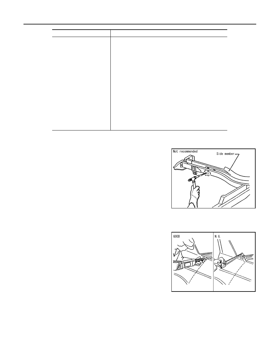
• The repair of reinforcements (such as side members) by heat-
ing is not recommended, because it may weaken the compo-
nent. When heating is unavoidable, never heat HSS parts
above 550
°
C (1,022
°
F).
Verify heating temperature with a thermometer.
(Crayon-type and other similar type thermometer are appropri-
ate.)
• When straightening body panels, use caution in pulling any HSS panel. Because HSS is very strong,
pulling may cause deformation in adjacent sections of the body. In this case, increase the number of
measuring points, and carefully pull the HSS panel.
• When cutting HSS panels, avoid gas (torch) cutting if possible.
Instead, use a saw to avoid weakening surrounding areas due
to heat. If gas (torch) cutting is unavoidable, allow a minimum
margin of 50 mm (1.97 in).
Tensile strength
Major applicable parts
980 - 1350 MPa
• Front side member rear extension
(Front floor assembly component part)
• Inner sill assembly
• Lower center dash crossmember assembly
• Front bumper reinforcement assembly
• Front side member closing plate (Rear)
(Side member closing plate assembly component part)
• Front side member (Rear)
(Front side member assembly component part)
• Inner center pillar (Upper)
(Inner center pillar assembly component part)
• Outer side roof rail
• Center pillar hinge brace (Upper)
(Center pillar hinge brace assembly component part)
• Outer front pillar reinforcement
(Front pillar hinge brace assembly component part)
• Outer sill reinforcement
(Outer sill reinforcement assembly component part)
• Rear bumper reinforcement assembly
PIIA0115E
PIIA0117E
REPAIRING HIGH STRENGTH STEEL
BRM-319
< PRECAUTION >
[EXCEPT FOR EUROPE AND RUSSIA (LHD)]
C
D
E
F
G
H
I
J
L
M
A
B
BRM
N
O
P
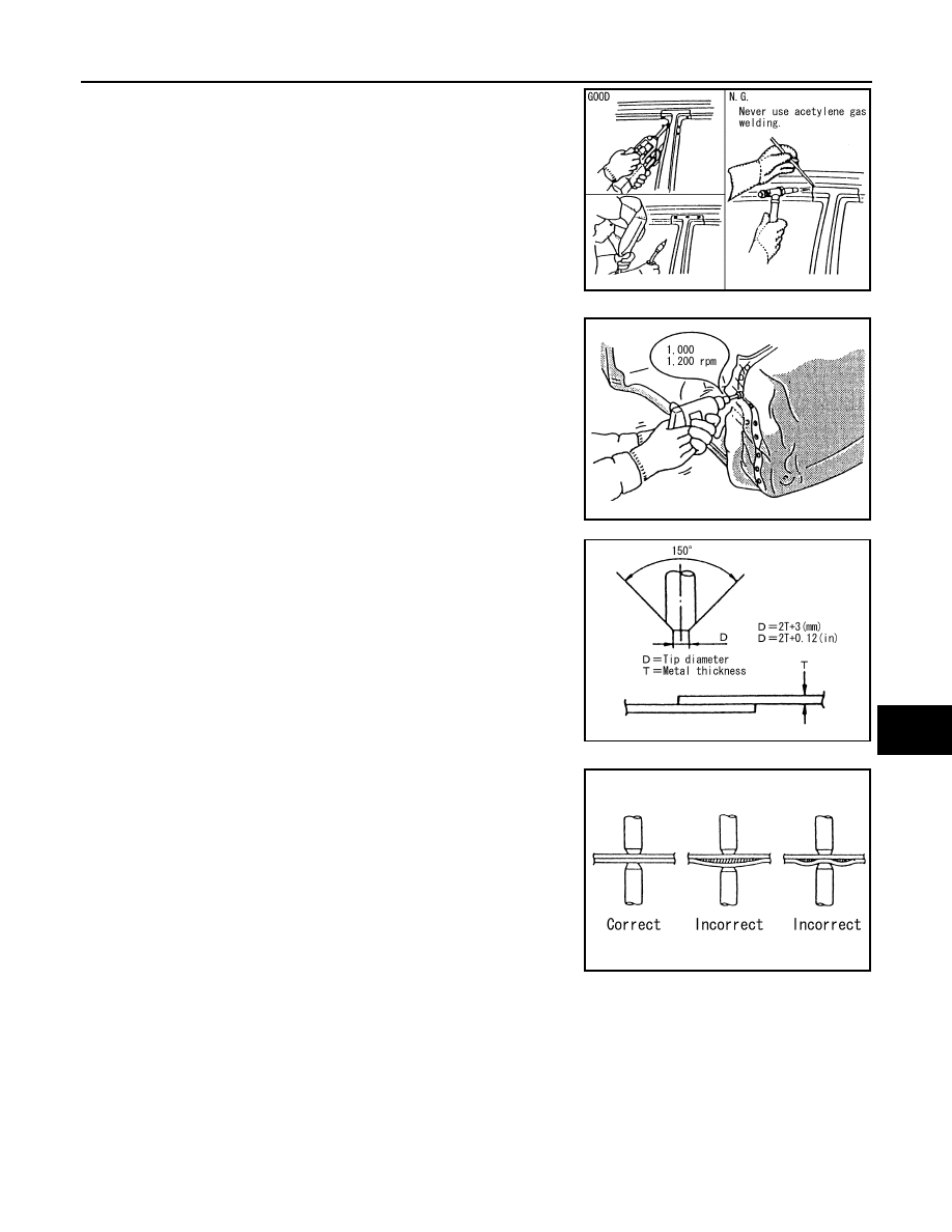
• When welding HSS panels, use spot welding whenever possi-
ble in order to minimize weakening surrounding areas due to
heat.
If spot welding is impossible, use MIG. welding. Do not use
gas (torch) for welding because it is inferior in welding
strength.
• Spot welding on HSS panels is harder than that of an ordinary
steel panel.
Therefore, when cutting spot welds on a HSS panel, use a low
speed high torque drill (1,000 to 1,200 rpm) to increase drill bit
durability and facilitate the operation.
2.
Precautions in spot welding HSS
This work should be performed under standard working condi-
tions. Always note the following when spot welding HSS:
• The electrode tip diameter must be sized properly according to
the metal thickness.
• The panel surfaces must fit flush to each other, leaving no
gaps.
PIIA0144E
PIIA0145E
PIIA0146E
PIIA0147E
BRM-320
< PRECAUTION >
[EXCEPT FOR EUROPE AND RUSSIA (LHD)]
REPAIRING HIGH STRENGTH STEEL
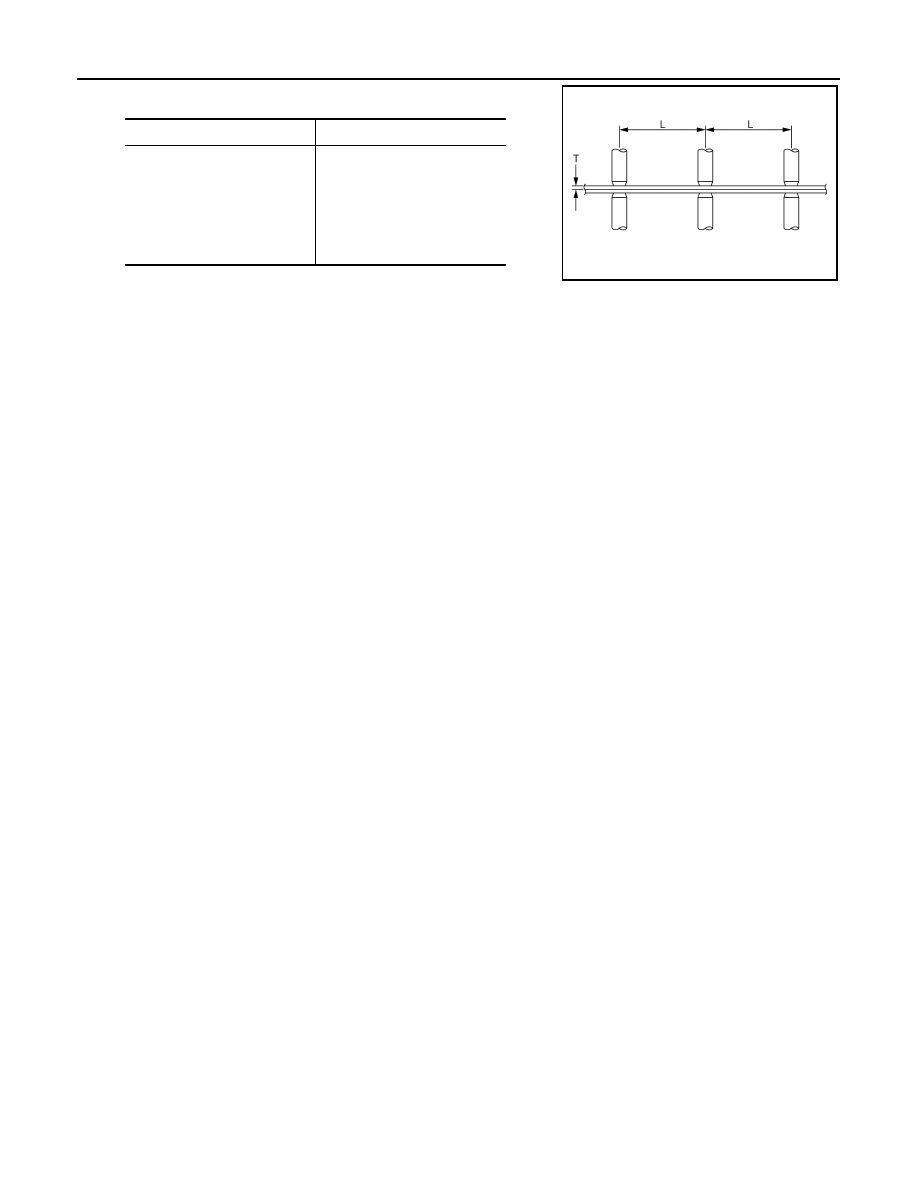
• Follow the specifications for the proper welding pitch.
Unit: mm (in)
Thickness (T)
Minimum pitch (L)
0.6 (0.024)
0.8 (0.031)
1.0 (0.039)
1.2 (0.047)
1.6 (0.063)
1.8 (0.071)
10 (0.39) or more
12 (0.47) or more
18 (0.71) or more
20 (0.79) or more
27 (1.06) or more
31 (1.22) or more
JSKIA0781ZZ
Нет комментариевНе стесняйтесь поделиться с нами вашим ценным мнением.
Текст