Qashqai J11. Defogger — part 2
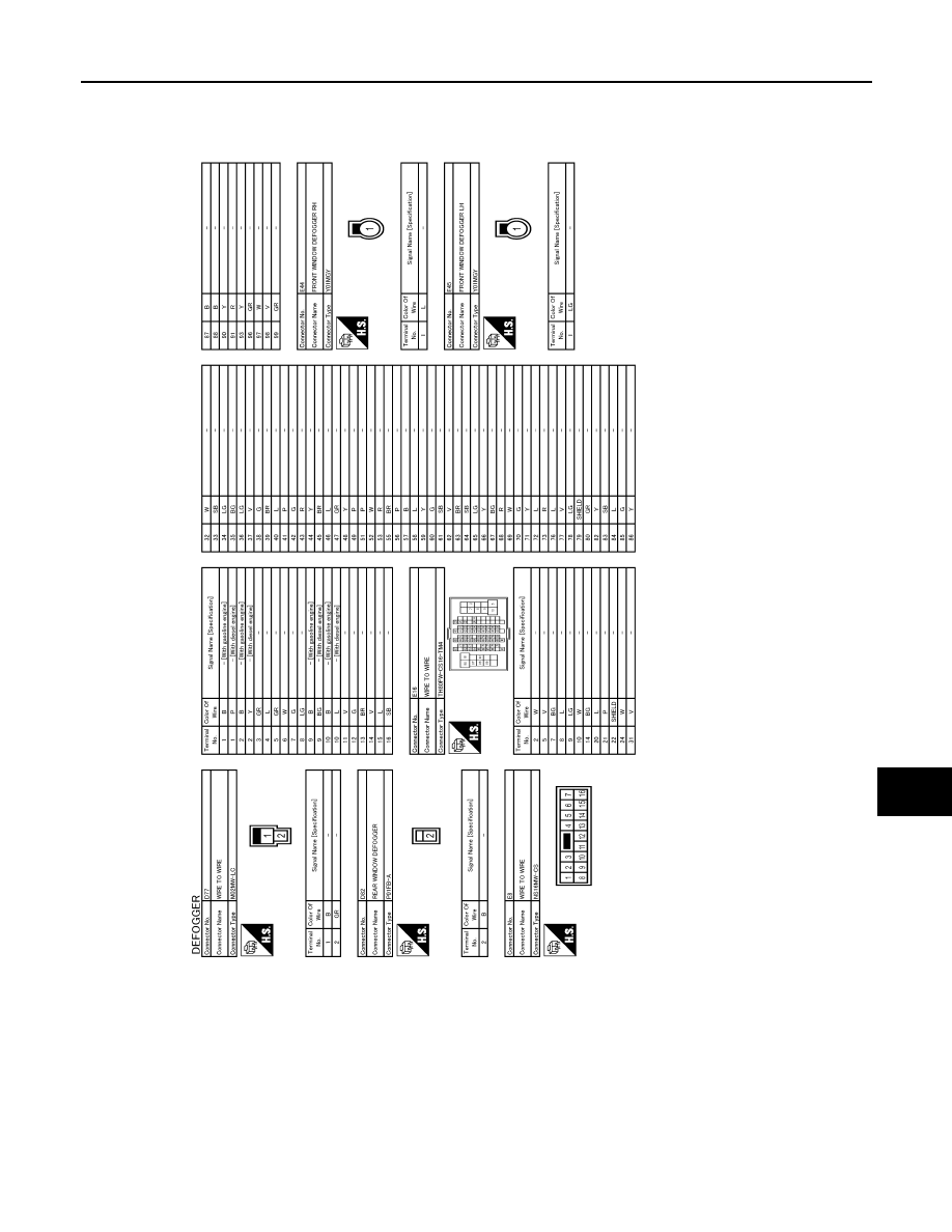
REAR WINDOW DEFOGGER SYSTEM
DEF-17
< WIRING DIAGRAM >
C
D
E
F
G
H
I
J
K
M
A
B
DEF
N
O
P
JRLWD2262GB
DEF-18
< WIRING DIAGRAM >
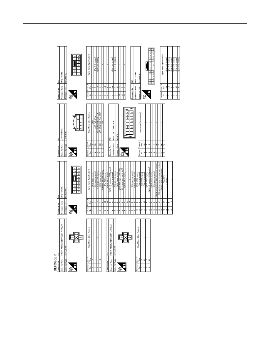
REAR WINDOW DEFOGGER SYSTEM
JRLWD2263GB
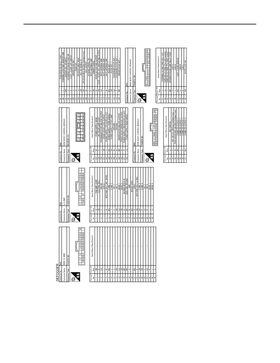
REAR WINDOW DEFOGGER SYSTEM
DEF-19
< WIRING DIAGRAM >
C
D
E
F
G
H
I
J
K
M
A
B
DEF
N
O
P
JRLWD2264GB
DEF-20
< WIRING DIAGRAM >
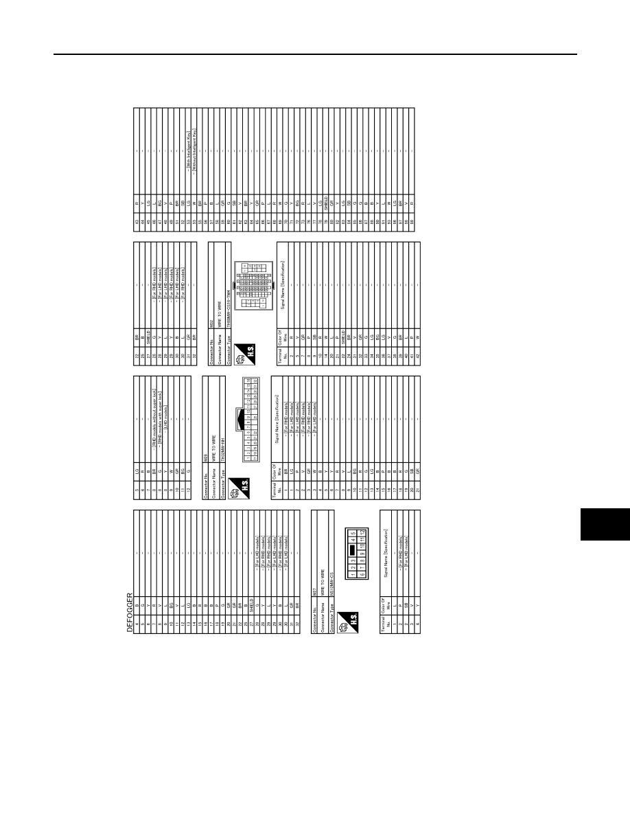
REAR WINDOW DEFOGGER SYSTEM
JRLWD2265GB

REAR WINDOW DEFOGGER SYSTEM
DEF-21
< WIRING DIAGRAM >
C
D
E
F
G
H
I
J
K
M
A
B
DEF
N
O
P
JRLWD2266GB
DEF-22
< BASIC INSPECTION >
DIAGNOSIS AND REPAIR WORK FLOW
BASIC INSPECTION
DIAGNOSIS AND REPAIR WORK FLOW
Work Flow
INFOID:0000000010434116
DETAILED FLOW
1.
OBTAIN INFORMATION ABOUT SYMPTOM
Interview the customer to obtain the malfunction information (conditions and environment when the malfunc-
tion occurred) as much as possible when the customer brings the vehicle in.
>> GO TO 2.
2.
CHECK DTC
Perform self diagnosis with CONSULT.
Is any DTC detected?
YES
>> Refer to
NO
>> GO TO 3.
3.
REPRODUCE THE MALFUNCTION INFORMATION
Check the malfunction on the vehicle that the customer describes.
Inspect the relation of the symptoms and the condition when the symptoms occur.
>> GO TO 4.
4.
IDENTIFY THE MALFUNCTIONING SYSTEM WITH “SYMPTOM DIAGNOSIS”
Use “Symptom diagnosis” from the symptom inspection result in step 3. Then identify where to start perform-
ing the diagnosis based on possible causes and symptoms.
>> GO TO 5.
5.
IDENTIFY MALFUNCTIONING PARTS WITH “COMPONENT DIAGNOSIS”
Perform the diagnosis with “Component diagnosis” of the applicable system.
>> GO TO 6.
6.
REPAIR OR REPLACE THE MALFUNCTIONING PARTS
Repair or replace the specified malfunctioning parts.
>> GO TO 7.
7.
FINAL CHECK
Check that malfunctions are not reproduced when obtaining the malfunction information from the customer,
referring to the symptom inspection result in step 3.
Are all malfunctions corrected?
YES
>> INSPECTION END
NO
>> GO TO 4.
REAR WINDOW DEFOGGER SWITCH
DEF-23
< DTC/CIRCUIT DIAGNOSIS >
C
D
E
F
G
H
I
J
K
M
A
B
DEF
N
O
P
DTC/CIRCUIT DIAGNOSIS
REAR WINDOW DEFOGGER SWITCH
Component Function Check
INFOID:0000000010434117
1.
CHECK REAR WINDOW DEFOGGER SWITCH FUNCTION
Check that the indicator lamp of rear window defogger illuminates when rear window defogger switch ON.
Is the inspection result normal?
YES
>> Rear window defogger switch function is OK.
NO
>> Refer to
Diagnosis Procedure
INFOID:0000000010434118
1.
CHECK A/C TYPE
Check A/C type.
Automatic A/C>>GO TO 2.
Except for automatic A/C>>GO TO 5.
2.
CHECK INTEGRAL SWITCH (REAR WINDOW DEFOGGER SWITCH)
Perform ON BOARD SELF-DIAGNOSIS of A/C control.
Refer to
HAC-45, "Diagnosis Description"
Is the inspection result normal?
YES
>> GO TO 4.
NO
>> GO TO 3.
3.
REPLACE A/C CONTROL
1.
Turn ignition switch OFF.
2.
Replace A/C control (rear window defogger switch). Refer to
HAC-126, "Removal and Installation"
.
3.
Turn ignition switch ON.
4.
Operate rear window defogger switch and check the operating condition.
Is the inspection result normal?
YES
>> INSPECTION END
NO
>> GO TO 4.
4.
REPLACE A/C AUTO AMP.
1.
Turn ignition switch OFF.
2.
Replace A/C auto amp. Refer to
HAC-127, "Removal and Installation"
3.
Turn ignition switch ON.
4.
Operate rear window defogger switch and check the operating condition.
Is the inspection result normal?
YES
>> INSPECTION END
NO
>> GO TO 6.
5.
REPLACE A/C AMP.
1.
Turn ignition switch OFF.
2.
Replace A/C amp. Refer to
HAC-222, "Removal and Installation"
(For models with manual A/C) or
289, "Removal and Installation"
(For models with manual heater).
3.
Turn ignition switch ON.
4.
Operate rear window defogger switch and check the operating condition.
Is the inspection result normal?
YES
>> INSPECTION END
NO
>> GO TO 6.
6.
CHECK INTERMITTENT INCIDENT
GI-41, "Intermittent Incident"
.
DEF-24
< DTC/CIRCUIT DIAGNOSIS >
REAR WINDOW DEFOGGER SWITCH
Is the inspection result normal?
>> INSPECTION END
REAR WINDOW DEFOGGER RELAY
DEF-25
< DTC/CIRCUIT DIAGNOSIS >
C
D
E
F
G
H
I
J
K
M
A
B
DEF
N
O
P
REAR WINDOW DEFOGGER RELAY
Component Function Check
INFOID:0000000010434119
1.
CHECK REAR WINDOW DEFOGGER RELAY POWER SUPPLY CIRCUIT
1.
Perform BCM Active Test (“REAR DEFOGGER”) with CONSULT.
2.
Touch “ON”.
3.
Check that the rear window heating wire is getting warmer.
Is the inspection result normal?
YES
>> Rear window defogger relay power supply circuit is OK.
NO
>> Refer to
Diagnosis Procedure
INFOID:0000000010434120
1.
CHECK REAR WINDOW DEFOGGER CIRCUIT 1
1.
Turn ignition switch ON.
2.
Check voltage between BCM harness connector and ground.
Is the inspection result normal?
YES
>> GO TO 5.
NO-1
>> Fixed at 0 V and remains unchanged: GO TO 2.
NO-2
>> Fixed at 9 – 16 V and remains unchanged: Replace BCM. Refer to
2.
CHECK REAR WINDOW DEFOGGER CIRCUIT 2
1.
Turn ignition switch OFF.
2.
Disconnect BCM connector and fuse block (J/B) connector.
3.
Check continuity between BCM harness connector and fuse block (J/B) harness connector.
Is the inspection result normal?
YES
>> GO TO 3.
NO
>> Repair or replace harness.
3.
CHECK REAR WINDOW DEFOGGER RELAY1
Check rear window defogger relay.
Refer to
DEF-26, "Component Inspection"
.
Is the inspection result normal?
YES
>> GO TO 4.
NO
>> Replace rear window defogger relay.
4.
CHECK FUSE BLOCK (J/B)
1.
Install the rear window defogger relay.
2.
Turn ignition switch ON.
3.
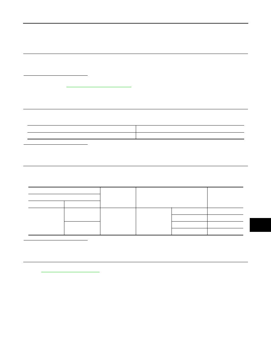
Check voltage between fuse block (J/B) (fuse block side) and ground.
(+)
(-)
Condition
Voltage (V)
BCM
Connector
Terminal
M70
64
Ground
Rear window defogger switch
ON
0 – 0.5
OFF
9 – 16
BCM
Fuse block (J/B)
Continuity
Connector
Terminal
Connector
Terminal
M70
64
M76
6B
Existed
DEF-26
< DTC/CIRCUIT DIAGNOSIS >
REAR WINDOW DEFOGGER RELAY
Is the inspection result normal?
YES
>> GO TO 6.
NO
>> Repair or replace fuse block (J/B).
5.
CHECK REAR WINDOW DEFOGGER RELAY2
1.
Turn ignition switch OFF.
2.
Check rear window defogger relay. Refer to
DEF-26, "Component Inspection"
.
Is the inspection result normal?
YES
>> INSPECTION END
NO
>> Replace rear window defogger relay.
6.
CHECK INTERMITTENT INCIDENT
GI-41, "Intermittent Incident"
Is the inspection result normal?
>> INSPECTION END
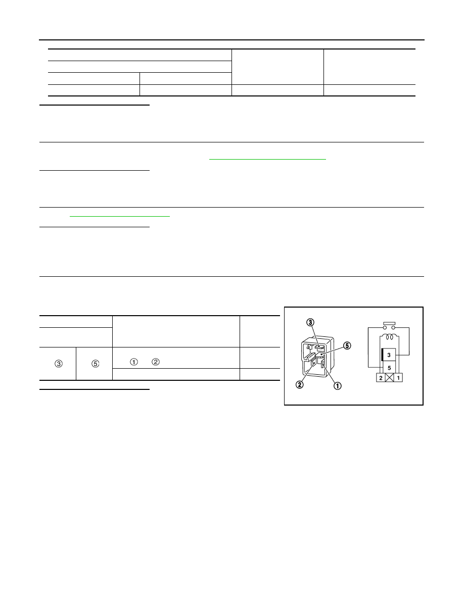
Component Inspection
INFOID:0000000010434121
1.
CHECK REAR WINDOW DEFOGGER RELAY
1.
Turn ignition switch OFF.
2.
Disconnect rear window defogger relay.
3.
Check continuity between rear window defogger relay terminals.
Is the inspection result normal?
YES
>> INSPECTION END
NO
>> Replace rear window defogger relay.
(+)
(-)
Voltage (V)
(Approx.)
Fuse block (J/B)
Connector
Terminal
M76
6B
Ground
Battery voltage
Terminal
Condition
Continuity
Rear window
defogger relay
12 V direct current supply between termi-
nals
and .
Existed
No current supply
Not existed
SEF497Y
REAR WINDOW DEFOGGER
DEF-27
< DTC/CIRCUIT DIAGNOSIS >
C
D
E
F
G
H
I
J
K
M
A
B
DEF
N
O
P
REAR WINDOW DEFOGGER
Component Function Check
INFOID:0000000010434122
1.
CHECK REAR WINDOW DEFOGGER
1.
Perform BCM Active Test (“REAR DEFOGGER”) with CONSULT.
2.
Touch “ON”.
3.
Check that the rear window heating wire is getting warmer.
Is the inspection result normal?
YES
>> Rear window defogger is OK.
NO
>> Refer to
Diagnosis Procedure
INFOID:0000000010434123
1.
CHECK FUSE
1.
Turn ignition switch OFF.
2.
Check that the following fuse is not fusing.
Is the inspection result normal?
YES
>> GO TO 2.
NO
>> Replace the blown fuse after repairing the affected circuit if a fuse is blown.
2.
CHECK POWER SUPPLY CIRCUIT
1.
Disconnect rear window defogger connector.
2.
Turn ignition switch ON.
3.
Check voltage between rear window defogger harness connector and ground.
Is the inspection result normal?
YES
>> GO TO 3.
NO
>> GO TO 4.
3.
CHECK GROUND CIRCUIT
1.
Turn ignition switch OFF.
2.
Check continuity between rear window defogger harness connector and ground.
Is the inspection result normal?
YES
>> GO TO 6.
NO
>> Repair or replace harness.
4.
CHECK REAR WINDOW DEFOGGER CIRCUIT
1.
Turn ignition switch OFF.
2.
Disconnect fuse block (J/B) connector.
Fuse No.
Capacity
10
15 A
11
(+)
(–)
Condition
Voltage (V)
(Approx.)
Rear window defogger
Connector
Terminal
B46
1
Ground
Rear window defogger
switch
ON
Battery voltage
OFF
0
Rear window defogger
Ground
Continuity
Connector
Terminal
D82
2
Existed
DEF-28
< DTC/CIRCUIT DIAGNOSIS >
REAR WINDOW DEFOGGER
3.
Check continuity between fuse block (J/B) harness connector and rear window defogger harness connec-
tor.
Is the inspection result normal?
YES
>> GO TO 5.
NO
>> Repair or replace harness.
5.
CHECK FUSE BLOCK (J/B)
1.
Turn ignition switch ON.
2.
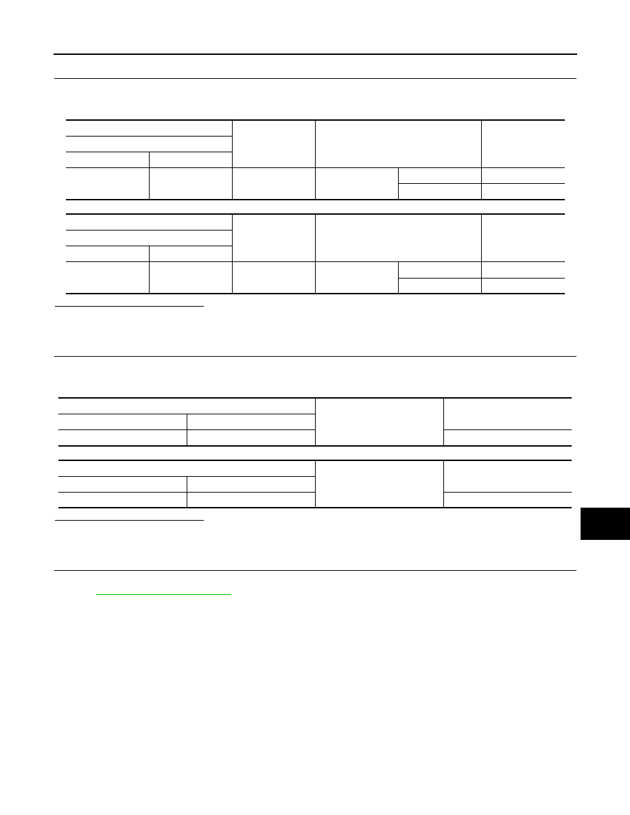
Check voltage between fuse block (J/B) (fuse block side) and ground.
Is the inspection result normal?
YES
>> GO TO 7.
NO
>> Replace fuse block (J/B).
6.
CHECK FILAMENT
Check the filament for damage or blown.
Refer to
DEF-42, "Inspection and Repair"
Is the inspection result normal?
YES
>> GO TO 7.
NO
>> Repair filament.
7.
CHECK INTERMITTENT INCIDENT
Check intermittent incident.
Refer to
DEF-42, "Inspection and Repair"
>> INSPECTION END
Fuse block (J/B)
Rear window defogger
Continuity
Connector
Terminal
Connector
Terminal
B35
3H
B46
1
Existed
5H
(+)
(–)
Condition
Voltage (V)
(Approx.)
Fuse block (J/B)
Connector
Terminal
B35
3H
Ground
Rear window defogger
switch
ON
Battery voltage
OFF
0
5H
ON
Battery voltage
OFF
0
DOOR MIRROR DEFOGGER
DEF-29
< DTC/CIRCUIT DIAGNOSIS >
C
D
E
F
G
H
I
J
K
M
A
B
DEF
N
O
P
DOOR MIRROR DEFOGGER
Component Function Check
INFOID:0000000010434125
1.
CHECK DOOR MIRROR DEFOGGER
1.
Perform BCM Active Test (“REAR DEFOGGER”) with CONSULT.
2.
Touch “ON”.
3.
Check that both side door mirror glass is getting warmer.
Is the inspection result normal?
YES
>> Door mirror defogger is OK.
NO
>> Refer to
Diagnosis Procedure
INFOID:0000000010434126
1.
CHECK FUSE
1.
Turn ignition switch OFF.
2.
Check that the following fuse is not fusing.
Is the inspection result normal?
YES
>> GO TO 2.
NO
>> Replace the blown fuse after repairing the affected circuit if a fuse is blown.
2.
CHECK FUSE BLOCK (J/B)
1.
Disconnect fuse block (J/B) connector.
2.
Turn ignition switch ON.
3.
Check voltage between fuse block (J/B) (fuse block side) and ground.
Is the inspection result normal?
YES
>> GO TO 3.
NO
>> Replace fuse block (J/B).
3.
CHECK INTERMITTENT INCIDENT
Check intermittent incident.
Refer to
GI-41, "Intermittent Incident"
.
>> INSPECTION END
Fuse No.
Capacity
12
10 A
(+)
(-)
Condition
Voltage (V)
(Approx.)
Fuse block (J/B)
Connector
Terminal
M76
4B
Ground
Rear window
defogger switch
ON
Battery voltage
OFF
0
5B
ON
Battery voltage
OFF
0

DEF-30
< DTC/CIRCUIT DIAGNOSIS >
DRIVER SIDE DOOR MIRROR DEFOGGER
DRIVER SIDE DOOR MIRROR DEFOGGER
Component Function Check
INFOID:0000000010434127
1.
CHECK DRIVER SIDE DOOR MIRROR DEFOGGER
1.
Perform BCM Active Test (“REAR DEFOGGER”) with CONSULT.
2.
Touch “ON”.
3.
Check that the driver side door mirror glass is getting warmer.
Is the inspection result normal?
YES
>> Driver side door mirror defogger is OK.
NO
>> Refer to
Diagnosis Procedure
INFOID:0000000010434128
1.
CHECK POWER SUPPLY CIRCUIT
1.
Turn ignition switch OFF.
2.
Disconnect door mirror (driver side) connector.
3.
Turn ignition switch ON.
4.
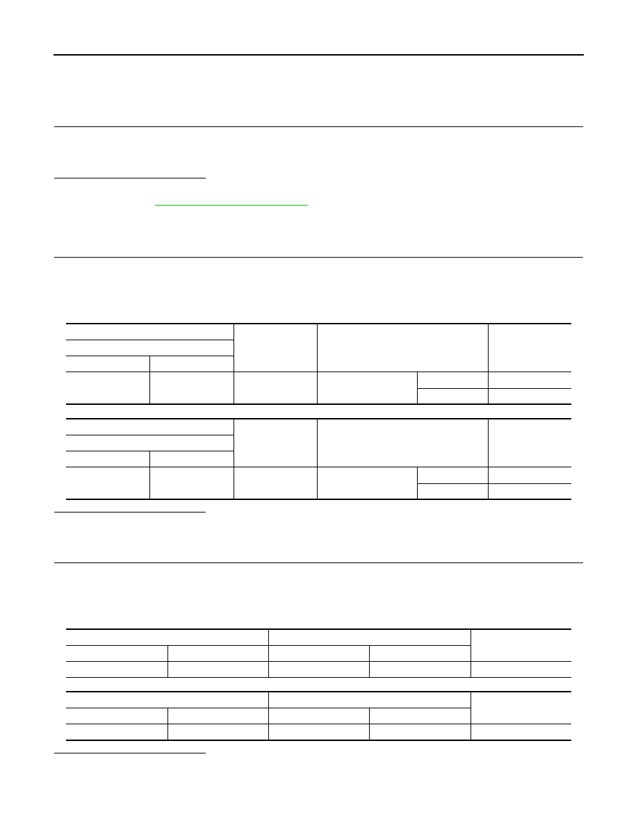
Check voltage between door mirror (driver side) harness connector and ground.
LHD
RHD
Is the inspection result normal?
YES
>> GO TO 4.
NO
>> GO TO 2.
2.
CHECK DRIVER SIDE DOOR MIRROR DEFOGGER CIRCUIT
1.
Turn ignition switch OFF.
2.
Disconnect fuse block (J/B) connector.
3.
Check continuity between fuse block (J/B) harness connector and door mirror (driver side) harness con-
nector.
LHD
RHD
Is the inspection result normal?
YES
>> GO TO 3.
NO
>> Repair or replace harness.
(+)
(-)
Condition
Voltage (V)
(Approx.)
Door mirror (driver side)
Connector
Terminal
D3
2
Ground
Rear window defogger
switch
ON
Battery voltage
OFF
0
(+)
(-)
Condition
Voltage (V)
(Approx.)
Door mirror (driver side)
Connector
Terminal
D40
2
Ground
Rear window defogger
switch
ON
Battery voltage
OFF
0
Fuse block (J/B)
Door mirror (driver side)
Continuity
Connector
Terminal
Connector
Terminal
M76
4B
D3
2
Existed
Fuse block (J/B)
Door mirror (driver side)
Continuity
Connector
Terminal
Connector
Terminal
M76
5B
D40
2
Existed
DRIVER SIDE DOOR MIRROR DEFOGGER
DEF-31
< DTC/CIRCUIT DIAGNOSIS >
C
D
E
F
G
H
I
J
K
M
A
B
DEF
N
O
P
3.
CHECK FUSE BLOCK (J/B)
1.
Turn ignition switch ON.
2.
Check voltage between fuse block (J/B) (fuse block side) and ground.
LHD
RHD
Is the inspection result normal?
YES
>> GO TO 5.
NO
>> Replace fuse block (J/B).
4.
CHECK GROUND CIRCUIT
1.
Turn ignition switch OFF.
2.
Check continuity between door mirror (driver side) harness connector and ground.
LHD
RHD
Is the inspection result normal?
YES
>> Replace glass mirror (driver side).
NO
>> Repair or replace harness.
5.
CHECK INTERMITTENT INCIDENT
Check intermittent incident.
Refer to
GI-41, "Intermittent Incident"
.
>> INSPECTION END
(+)
(-)
Condition
Voltage (V)
(Approx.)
Fuse block (J/B)
Connector
Terminal
M76
4B
Ground
Rear window
defogger switch
ON
Battery voltage
OFF
0
(+)
(-)
Condition
Voltage (V)
(Approx.)
Fuse block (J/B)
Connector
Terminal
M76
5B
Ground
Rear window
defogger switch
ON
Battery voltage
OFF
0
Door mirror (driver side)
Ground
Continuity
Connector
Terminal
D3
10
Existed
Door mirror (driver side)
Ground
Continuity
Connector
Terminal
D40
10
Existed
DEF-32
< DTC/CIRCUIT DIAGNOSIS >
PASSENGER SIDE DOOR MIRROR DEFOGGER
PASSENGER SIDE DOOR MIRROR DEFOGGER
Component Function Check
INFOID:0000000010434129
1.
CHECK PASSENGER SIDE DOOR MIRROR DEFOGGER
1.
Perform BCM Active Test (“REAR DEFOGGER”) with CONSULT.
2.
Touch “ON”.
3.
Check that the passenger side door mirror glass is getting warmer.
Is the inspection result normal?
YES
>> Passenger side door mirror defogger is OK.
NO
>> Refer to
.
Diagnosis Procedure
INFOID:0000000010505198
1.
CHECK POWER SUPPLY CIRCUIT
1.
Turn ignition switch OFF.
2.
Disconnect door mirror (passenger side) connector.
3.
Turn ignition switch ON.
4.
Check voltage between door mirror (passenger side) harness connector and ground.
LHD
RHD
Is the inspection result normal?
YES
>> GO TO 4.
NO
>> GO TO 2.
2.
CHECK PASSENGER SIDE DOOR MIRROR DEFOGGER CIRCUIT
1.
Turn ignition switch OFF.
2.
Disconnect fuse block (J/B) connector.
3.
Check continuity between fuse block (J/B) harness connector and door mirror (passenger side) harness
connector.
LHD
RHD
Is the inspection result normal?
YES
>> GO TO 3.
NO
>> Repair or replace harness.
(+)
(-)
Condition
Voltage (V)
(Approx.)
Door mirror (passenger side)
Connector
Terminal
D27
2
Ground
Rear window defogger
switch
ON
Battery voltage
OFF
0
(+)
(-)
Condition
Voltage (V)
(Approx.)
Door mirror (passenger side)
Connector
Terminal
D16
2
Ground
Rear window defogger
switch
ON
Battery voltage
OFF
0
Fuse block (J/B)
Door mirror (passenger side)
Continuity
Connector
Terminal
Connector
Terminal
M76
5B
D27
2
Existed
Fuse block (J/B)
Door mirror (passenger side)
Continuity
Connector
Terminal
Connector
Terminal
M76
4B
D16
2
Existed
Нет комментариевНе стесняйтесь поделиться с нами вашим ценным мнением.
Текст