Nissan March K13. Manual — part 413
INL-32
< DTC/CIRCUIT DIAGNOSIS >
PUSH-BUTTON IGNITION SWITCH ILLUMINATION CIRCUIT
PUSH-BUTTON IGNITION SWITCH ILLUMINATION CIRCUIT
Component Function Check
INFOID:0000000006043808
1.
CHECK PUSH-BUTTON IGNITION SWITCH ILLUMINATION OPERATION
CONSULT-III ACTIVE TEST
1.
Turn the ignition switch ON.
2.
Select “ENGINE SW ILLUMI” of BCM (INTELLIGENT KEY) active test item.
3.
With operating the test items, check that the push-button ignition switch illumination turns ON/OFF.
Does the push-button ignition switch illumination turn ON/OFF?
YES
>> Push-button ignition switch illumination circuit is normal.
NO
>> Refer to
.
Diagnosis Procedure
INFOID:0000000006043809
1.
CHECK PUSH-BUTTON IGNITION SWITCH ILLUMINATION POWER SUPPLY OUTPUT
1.
Turn the ignition switch OFF.
2.
Disconnect push-button ignition switch connector.
3.
Check voltage between push-button ignition switch harness connector and ground.
Is the inspection result normal?
YES
>> GO TO 4.
NO
>> GO TO 2.
2.
CHECK PUSH-BUTTON IGNITION SWITCH ILLUMINATION POWER SUPPLY OPEN CIRCUIT
1.
Disconnect BCM connector.
2.
Check continuity between BCM harness connector and the push-button ignition switch harness connector.
Is the inspection result normal?
YES
>> GO TO 3.
NO
>> Repair or replace harnesses.
3.
CHECK PUSH-BUTTON IGNITION SWITCH ILLUMINATION POWER SUPPLY SHORT CIRCUIT
Check continuity between BCM harness connector and ground.
Is the inspection result normal?
YES
>> Replace BCM. Refer to
BCS-57, "Removal and Installation"
(With intelligent Key),
(Without intelligent Key).
NO
>> Repair or replace harnesses.
On
: Push-button ignition switch illumination ON
Off
: Push-button ignition switch illumination OFF
(+)
(–)
Condition
Voltage
(Approx.)
Push-button ignition switch
Connector
Terminal
M101
5
Ground
Push-button ignition switch il-
lumination
ON
12 V
OFF
0 V
BCM
Push-button ignition switch
Continuity
Connector
Terminal
Connector
Terminal
M71
90
M101
5
Existed
BCM
Ground
Continuity
Connector
Terminal
M71
90
Not existed
PUSH-BUTTON IGNITION SWITCH ILLUMINATION CIRCUIT
INL-33
< DTC/CIRCUIT DIAGNOSIS >
C
D
E
F
G
H
I
J
K
M
A
B
INL
N
O
P
4.
CHECK PUSH-BUTTON IGNITION SWITCH ILLUMINATION GROUND CIRCUIT
Check continuity between push-button ignition switch harness connector and ground.
Is the inspection result normal?
YES
>> Replace push-button ignition switch.
NO
>> Repair or replace harnesses.
Push-button ignition switch
Ground
Continuity
Connector
Terminal
M101
6
Existed
INL-34
< SYMPTOM DIAGNOSIS >
INTERIOR LIGHTING SYSTEM SYMPTOMS
SYMPTOM DIAGNOSIS
INTERIOR LIGHTING SYSTEM SYMPTOMS
Symptom Table
INFOID:0000000006030919
CAUTION:
Perform the self-diagnosis with CONSULT-III before the symptom diagnosis. Perform the trouble diag-
nosis if any DTC is detected.
Symptom
Possible cause
Inspection item
• Interior room lamp does not turn ON even
though the door is open.
(It turns ON when turning the interior room
lamp ON.)
• Interior room lamp does not turn OFF even
though the door is closed.
• Harness between BCM and each
door switch
• Harness between BCM and each
interior room lamp
• BCM
Door switch circuit
Refer to
(with Intelligent Key),
XX-XX, "*****"
(without Intelligent
Key).
Interior room lamp control circuit
Refer to
Interior room lamp timer does not activate.
(It turns ON/ OFF when the door opens/closes.)
—
Check the interior room lamp setting.
Refer to
Push-button ignition switch illumination does not
illuminate.
• Harness between BCM and push-
button ignition switch
• Harness between push-button igni-
tion switch and ground
• Push-button ignition switch
• BCM
Push-button ignition switch illumina-
tion circuit
Refer to
Interior room lamp battery saver does not acti-
vate.
—
Check the interior room lamp battery
saver setting.
Refer to
MAP LAMP
INL-35
< REMOVAL AND INSTALLATION >
C
D
E
F
G
H
I
J
K
M
A
B
INL
N
O
P
REMOVAL AND INSTALLATION
MAP LAMP
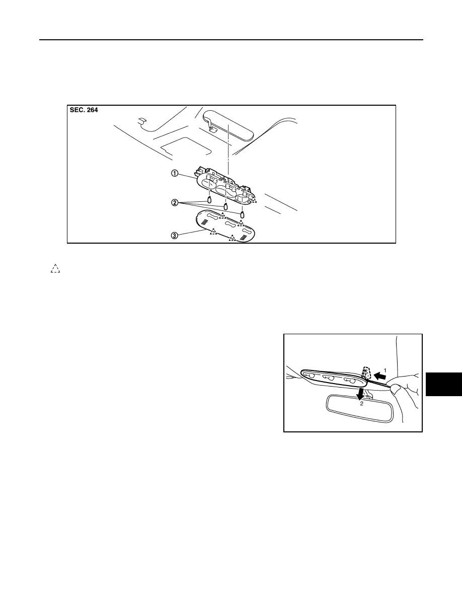
Exploded View
INFOID:0000000006030920
Removal and Installation
INFOID:0000000006030921
CAUTION:
Disconnect the battery negative terminal or the fuse.
REMOVAL
1.
Insert any appropriate tool into the gap between the map lamp
bulb housing to the headlining. And press the pawl and then pull
the map lamp .
2.
Disconnect the connector.
INSTALLATION
Install in the reverse order of removal.
Replacement
INFOID:0000000006030922
CAUTION:
• Disconnect the battery negative terminal or the fuse.
• Never touch the glass of bulb directly by hand. Keep grease and other oily matters away from it.
• Never touch bulb by hand while it is lit or right after being turned off.
• Never leave bulb out of lamp reflector for a long time because dust, moisture smoke, etc. may affect
the performance of lamp. When replacing bulb, be sure to replace it with new one.
1.
Map lamp bulb housing
2.
Bulb
3.
Lens
: Pawl
JMLIA0707ZZ
JSLIA0110ZZ
Нет комментариевНе стесняйтесь поделиться с нами вашим ценным мнением.
Текст