Nissan March K13. Manual — part 287
EM-82
< UNIT REMOVAL AND INSTALLATION >
[HR12DE]
ENGINE ASSEMBLY
1.
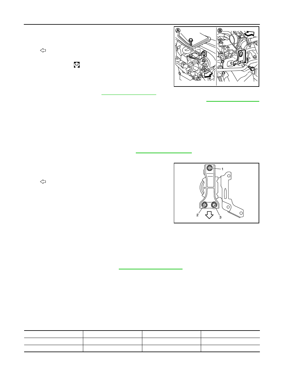
When engine can be hoisted, install engine slinger to cylinder
head front left side (A) and rear right side (B) and support the
engine position with a hoist.
2.
Remove starter motor. Refer to
.
3.
Lift with a hoist and separate the engine from the transaxle assembly. Refer to
(M/T models).
INSTALLATION
Note the following, and install in the reverse order of removal.
CAUTION:
• Never allow engine oil to get on engine mounting insulator. Be careful not to damage engine mount-
ing insulator.
• Check that each mounting insulator is seated properly, and tighten mounting nuts and bolts.
• When installation directions are specified, install parts according to the direction marks on them
referring to the figure of components. Refer to
Engine Mounting Bracket (RH)
• Tighten mounting bolts in the numerical order as shown in the fig-
ure.
Inspection
INFOID:0000000005988207
INSPECTION AFTER INSTALLATION
Inspection for Leakage
The following are procedures for checking fluids leakage, lubricates leakage, and exhaust gases leakage.
• Before starting engine, check oil/fluid levels including engine coolant and engine oil. If less than required
quantity, fill to the specified level. Refer to
.
• Use procedure below to check for fuel leakage.
- Turn ignition switch “ON” (with engine stopped). With fuel pressure applied to fuel piping, check for fuel leak-
age at connection points.
- Start engine. With engine speed increased, check again for fuel leakage at connection points.
• Run engine to check for unusual noise and vibration.
• Warm up engine thoroughly to check there is no leakage of fuel, exhaust gases, or any oil/fluids including
engine oil and engine coolant.
• Bleed air from lines and hoses of applicable lines, such as in cooling system.
• After cooling down engine, again check oil/fluid levels including engine oil and engine coolant. Refill to the
specified level, if necessary.
Summary of the inspection items:
: Engine front
Slinger bolts
: 25.0 N·m (2.6 kg-m, 18 ft-lb)
JPBIA3409ZZ
: Vehicle front
JPBIA2809ZZ
Items
Before starting engine
Engine running
After engine stopped
Engine coolant
Level
Leakage
Level
Engine oil
Level
Leakage
Level
ENGINE ASSEMBLY
EM-83
< UNIT REMOVAL AND INSTALLATION >
[HR12DE]
C
D
E
F
G
H
I
J
K
L
M
A
EM
N
P
O
*: Transmission/transaxle/CVT fluid, power steering fluid, brake fluid, etc.
Other oils and fluid*
Level
Leakage
Level
Fuel
Leakage
Leakage
Leakage
Exhaust gases
—
Leakage
—
EM-84
< UNIT DISASSEMBLY AND ASSEMBLY >
[HR12DE]
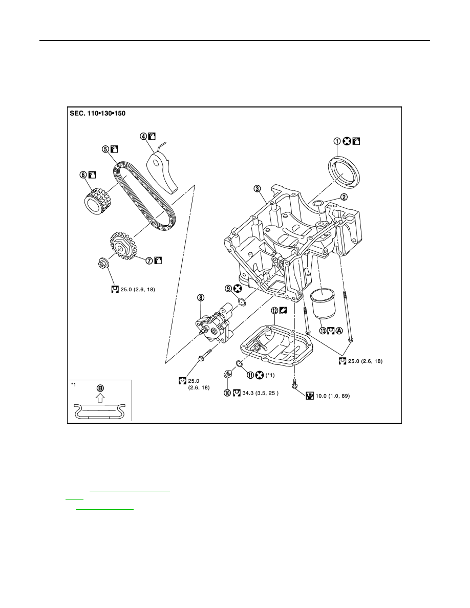
OIL PAN (UPPER)
UNIT DISASSEMBLY AND ASSEMBLY
OIL PAN (UPPER)
Exploded View
INFOID:0000000005988211
1.
Rear oil seal
2.
O-ring
3.
Oil pan (upper)
4.
Oil pump chain tensioner
5.
Oil pump drive chain
6.
Crankshaft sprocket
7.
Oil pump sprocket
8.
Oil pump
9.
O-ring
10. Drain plug
11.
Drain plug washer
12. Oil pan (lower)
13. Oil filter
A.
B.
Oil pan (lower) side
Refer to
for symbols in the figure.
JPBIA3384GB
CYLINDER BLOCK
EM-85
< UNIT DISASSEMBLY AND ASSEMBLY >
[HR12DE]
C
D
E
F
G
H
I
J
K
L
M
A
EM
N
P
O
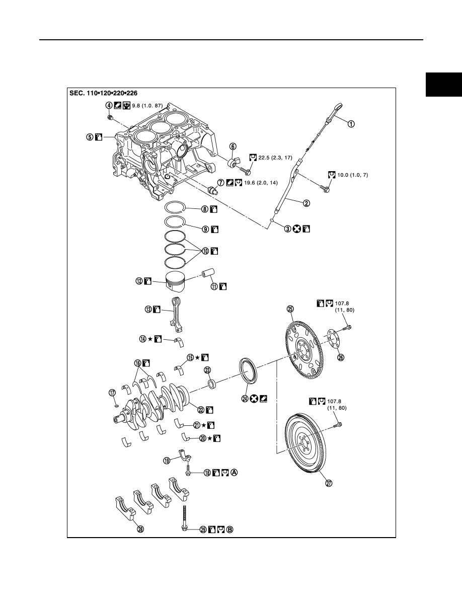
CYLINDER BLOCK
Exploded View
INFOID:0000000005988214
1.
Oil level gauge
2.
Oil level gauge guide
3.
O-ring
4.
Drain plug
5.
Cylinder block
6.
Knock sensor
7.
Oil pressure switch
8.
Top ring
9.
Second ring
JPBIA3394GB
Нет комментариевНе стесняйтесь поделиться с нами вашим ценным мнением.
Текст