Nissan March K13. Manual — part 13
BCS
BCM
BCS-25
< ECU DIAGNOSIS INFORMATION >
[WITH INTELLIGENT KEY SYSTEM]
C
D
E
F
G
H
I
J
K
L
B
A
O
P
N
9
(W)
Ground
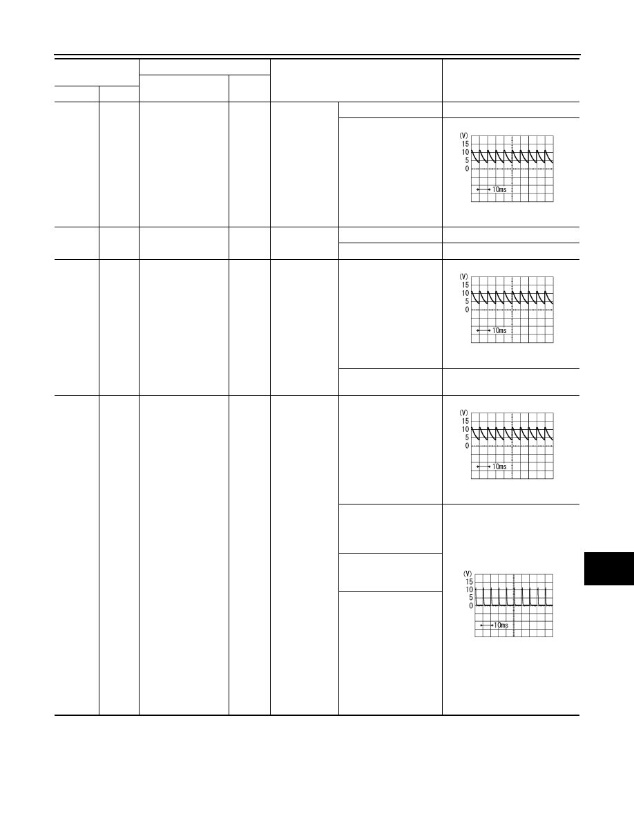
Stop lamp switch 1
Input
Stop lamp
switch
OFF (Brake pedal is not
depressed)
0 V
ON (Brake pedal is de-
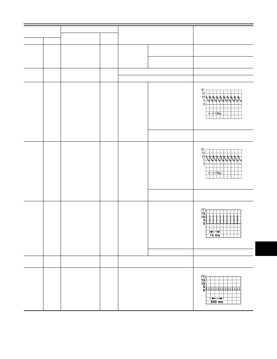
pressed)
Battery voltage
11
(L)
Ground
ACC feedback
Input
Ignition switch OFF
0 V
Ignition switch ACC or ON
Battery voltage
12
(P)
Ground
Passenger door
switch
Input
Passenger
door switch
OFF (When passenger
door closed)
7.0 - 8.0 V
ON (When passenger
door opened)
0 V
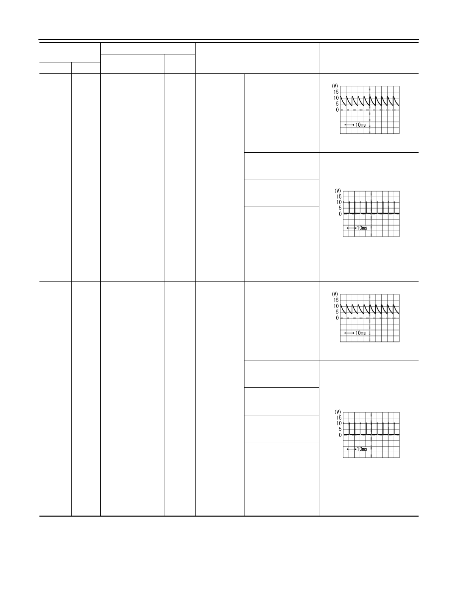
13
(LG)
Ground
Rear RH door switch
Input
Rear RH door
switch
OFF (When rear RH
door closed)
7.0 - 8.0 V
ON (When rear RH door
opened)
0 V
15
(G)
Ground
Rear window defog-
ger switch
Input
Rear window
defogger
switch
Not pressed
1.0 - 1.5 V
Pressed
0 V
18
(V)
Ground
Receiver and sensor
ground
Input
Ignition switch ON
0 V
19
(LG)
Ground
Remote keyless en-
try receiver power
supply
Output
Ignition switch OFF
Terminal No.
(Wire color)
Description
Condition
Value
(Approx.)
Signal name
Input/
Output
+
−
PKIB4960J
PKIB4960J
JPMIA0012GB
JMKIA3838GB
BCS-26
< ECU DIAGNOSIS INFORMATION >
[WITH INTELLIGENT KEY SYSTEM]
BCM
20
(G)
Ground
Remote keyless en-
try receiver commu-
nication
Input
Waiting
Signal receiving
21
(P)
Ground
NATS antenna amp.
Input/
Output
During waiting
Intelligent Key backside
is contacted to push-but-
ton ignition switch, turn
ignition switch ON.
Just after pressing push-button
ignition switch. Pointer of analog
tester should move.
22
(W)
Ground
Remote keyless en-
try receiver RSSI
Input
Waiting
0 V
Signal receiving
23
(G)
Ground
Security indicator
lamp
Output
Security indi-
cator lamp
ON
0 V
Blinking (Ignition switch
OFF)
12.0 V
OFF
12 V
25
(LG)
Ground
NATS antenna amp.
Input/
Output
During waiting
Intelligent Key backside
is contacted to push-but-
ton ignition switch, turn
ignition switch ON.
Just after pressing push-button
ignition switch. Pointer of analog
tester should move.
27
(W)
Ground
A/C switch
Input
A/C
OFF (A/C switch indica-
tor: OFF)
1.0 - 1.5 V
ON (A/C switch indica-
tor: ON)
0 V
Terminal No.
(Wire color)
Description
Condition
Value
(Approx.)
Signal name
Input/
Output
+
−
JMKIA3838GB
JMKIA3841GB
JMKIA3838GB
JPMIA0590GB
JPMIA0012GB
BCS
BCM
BCS-27
< ECU DIAGNOSIS INFORMATION >
[WITH INTELLIGENT KEY SYSTEM]
C
D
E
F
G
H
I
J
K
L
B
A
O
P
N
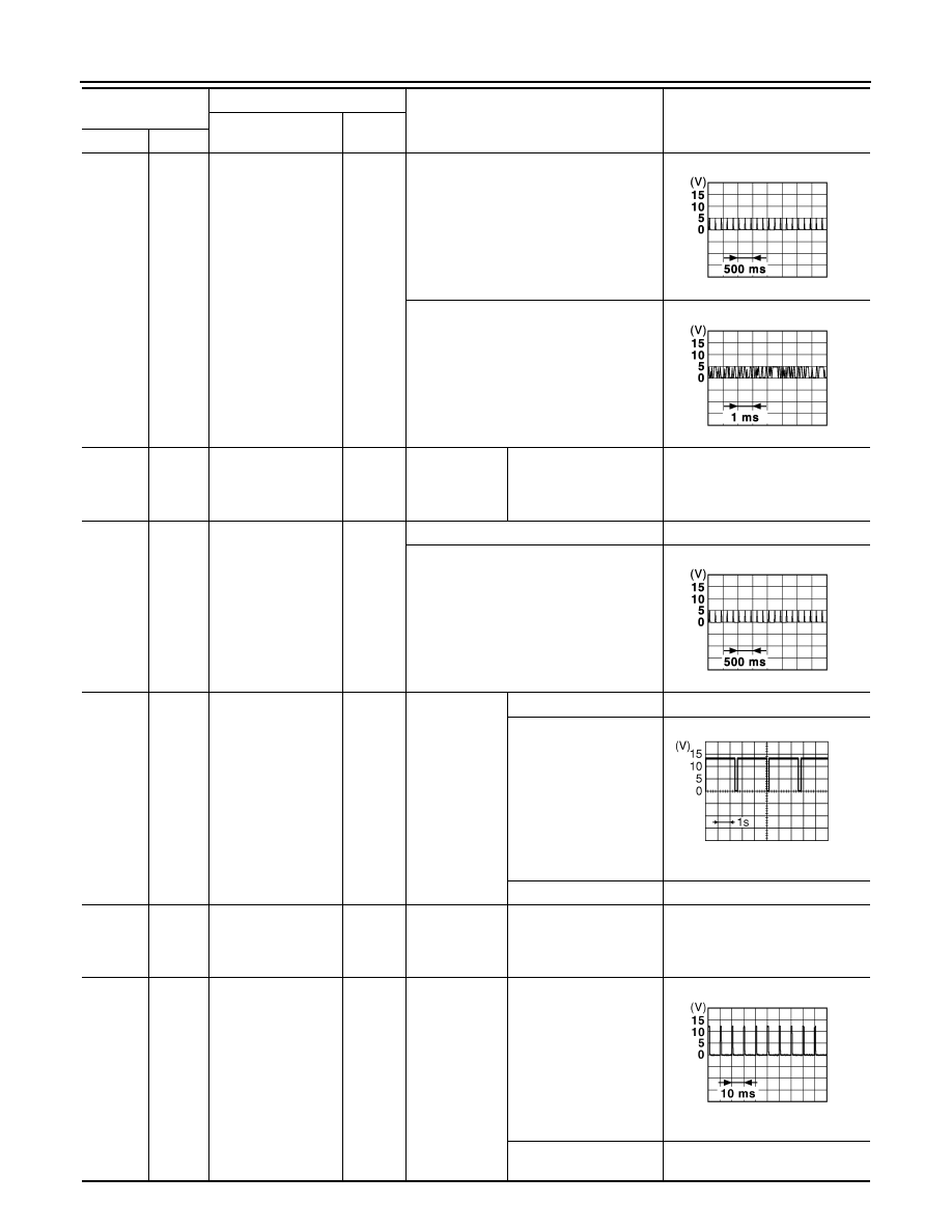
28
(SB)
Ground
Blower fan switch
Input
Fan switch
Blower fan switch OFF
0 V
Blower fan switch ON
7.0 - 8.0 V
29
(SB)
Ground
Hazard switch
Input
Hazard switch
OFF
12 V
ON
0 V
31
(Y)
Ground
Front door lock as-
sembly driver side
(Unlock sensor)
Input
Driver door
LOCK status (Unlock
sensor switch OFF)
7.0 - 8.0 V
UNLOCK status (Unlock
sensor switch ON)
0 V
32
(P)
Ground
Combination switch
OUTPUT 5
Output
Combination
switch
All switches OFF
(Wiper intermittent dial
4)
7.0 - 8.0 V
Front fog lamp switch
ON
(Wiper intermittent dial
4)
1.0 V
Rear wiper switch ON
(Wiper intermittent dial
4)
Any of the condition be-
low with all switches
OFF
• Wiper intermittent dial
1
• Wiper intermittent dial
2
• Wiper intermittent dial
6
• Wiper intermittent dial
7
Terminal No.
(Wire color)
Description
Condition
Value
(Approx.)
Signal name
Input/
Output
+
−
PKIB4960J
PKIB4960J
PKIB4960J
PKIB4956J
BCS-28
< ECU DIAGNOSIS INFORMATION >
[WITH INTELLIGENT KEY SYSTEM]
BCM
33
(V)
Ground
Combination switch
OUTPUT 4
Output
Combination
switch
All switches OFF
(Wiper intermittent dial
4)
7.0 - 8.0 V
Lighting switch 1ST
(Wiper intermittent dial
4)
1.2 V
Rear wiper switch INT
(Wiper intermittent dial
4)
Any of the condition be-
low with all switches
OFF
• Wiper intermittent dial
1
• Wiper intermittent dial
5
• Wiper intermittent dial
6
34
(W)
Ground
Combination switch
OUTPUT 3
Output
Combination
switch
All switches OFF
(Wiper intermittent dial
4)
7.0 - 8.0 V
Lighting switch 2ND
(Wiper intermittent dial
4)
1.2 V
Lighting switch HI
(Wiper intermittent dial
4)
Rear washer switch ON
(Wiper intermittent dial
4)
Any of the condition be-
low with all switches
OFF
• Wiper intermittent dial
1
• Wiper intermittent dial
2
• Wiper intermittent dial
3
Terminal No.
(Wire color)
Description
Condition
Value
(Approx.)
Signal name
Input/
Output
+
−
PKIB4960J
PKIB4958J
PKIB4960J
PKIB4958J
Нет комментариевНе стесняйтесь поделиться с нами вашим ценным мнением.
Текст