Nissan March K13. Manual — part 389
HAC-90
< SYSTEM DESCRIPTION >
[MANUAL AIR CONDITIONER]
SYSTEM
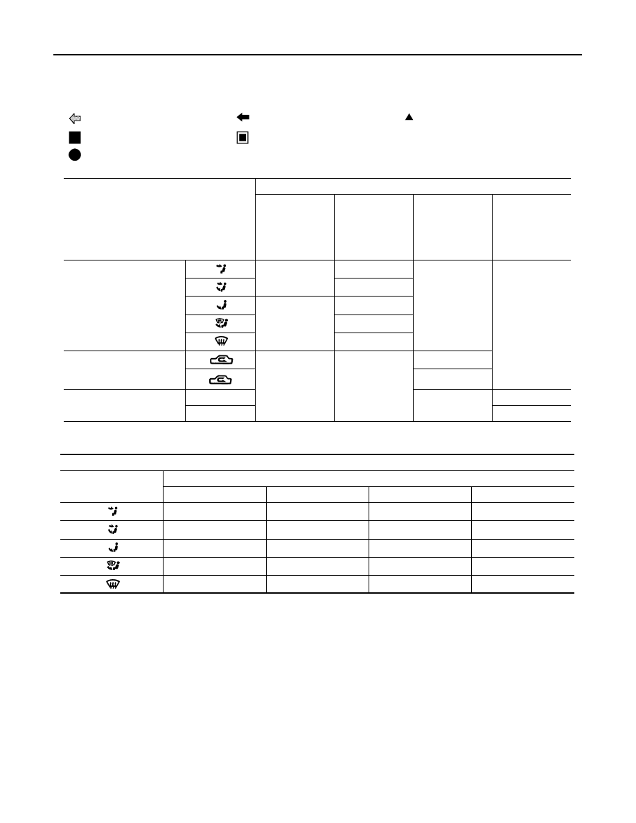
AIR DISTRIBUTION
1.
Intake door
2.
Blower motor
3.
Evaporator
4.
Air mix door
5.
Heater core
6.
Foot door
7.
Ventilator and defroster door
Fresh air intake
Recirculation air
Defroster
Center ventilator
Side ventilator
Foot
Switch/Dial
position
Door position
V
e
n
til
ato
r an
d
def
ros
ter do
or
F
o
ot
do
or
In
ta
ke
do
or
A
ir m
ix
do
or
MODE dial
B
A
—
—
A – B
A
B
A – B
A
Air intake lever
—
—
B
A
Temperature control dial
Full cold
—
A
Full hot
B
Discharge air flow
Mode position indication
Air outlet/distribution
Center ventilator
Side ventilator
Foot
Defroster
50%
50%
—
—
30%
30%
40%
—
7%
7%
66%
20%
7%
7%
51%
35%
—
22%
—
78%
OPERATION
HAC-91
< SYSTEM DESCRIPTION >
[MANUAL AIR CONDITIONER]
C
D
E
F
G
H
J
K
L
M
A
B
HAC
N
O
P
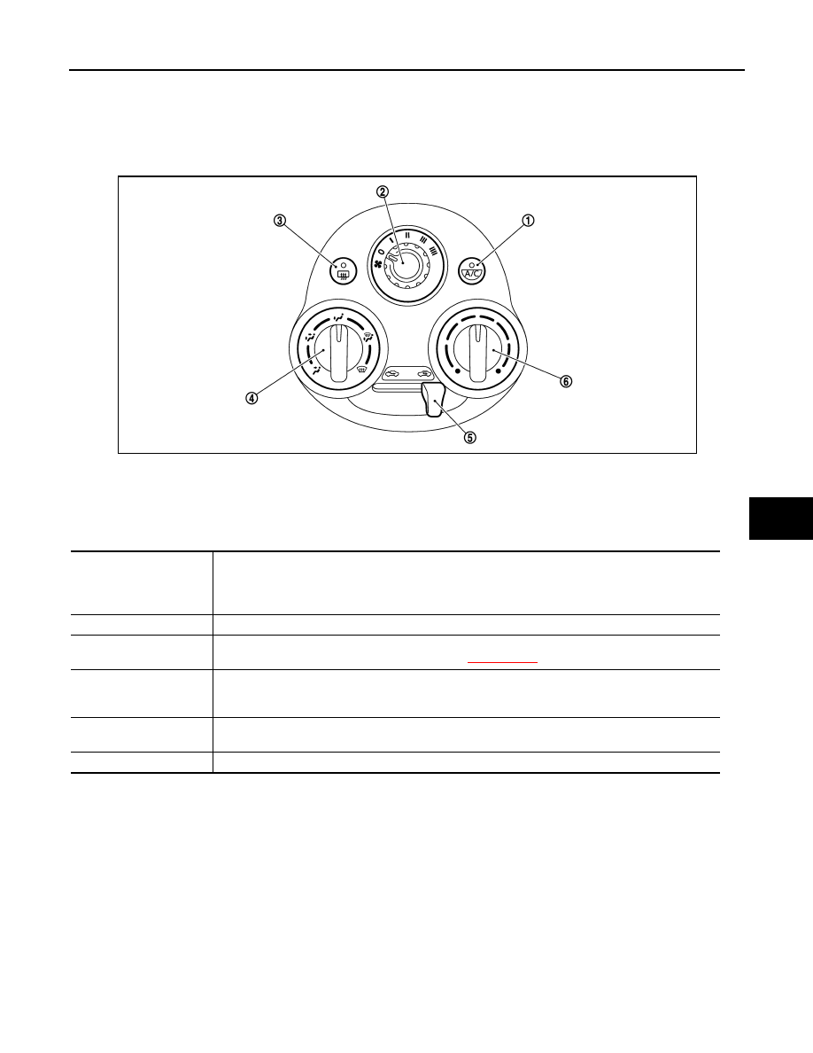
OPERATION
Switch Name and Function
INFOID:0000000006043971
CONTROLLER
SWITCH OPERATION
1.
A/C switch
2.
Fan control dial
3.
Rear window defogger switch
4.
MODE dial
5.
Air intake lever
6.
Temperature control dial
JMIIA0702ZZ
A/C switch
The compressor control (switch indicator) is turned ON
⇔
OFF each time by pressing this switch
while the blower motor is activated.
NOTE:
when mode position is D/F or DEF, A/C switch is turned ON forcibly.
Fan control dial
Fan speed can be adjusted within a range from 1st to 4th.
Rear window defogger
switch
• Rear window defogger (switch indicator) is turned ON
⇔
OFF each time by pressing this switch.
• Rear window defogger system details, Refer to
XX-XX, "*****"
.
MODE dial
• Mode position is selected to an optimal position by operating this dial.
• When DEF or D/F is selected while blower motor is activated, the air conditioner will automatically
turn on and the air inlet becomes fresh air intake.
Air intake lever
• Recirculation (REC) position: Interior air is recirculated inside the vehicle.
• Fresh (FRE) position: Outside air is drawn into the passenger compartment.
Temperature control dial
The setting temperature can be selected to an optimum temperature by operating this dial.

HAC-92
< SYSTEM DESCRIPTION >
[MANUAL AIR CONDITIONER]
DIAGNOSIS SYSTEM (BCM)
DIAGNOSIS SYSTEM (BCM)
COMMON ITEM
COMMON ITEM : CONSULT-III Function (BCM - COMMON ITEM)
INFOID:0000000006024110
APPLICATION ITEM
CONSULT-III can display each diagnostic item using the diagnostic test modes shown following.
SYSTEM APPLICATION
BCM can perform the following functions for each system.
NOTE:
It can perform the diagnosis modes except the following for all sub system selection items.
×
: Applicable item
*: This item is displayed, but is not function.
AIR CONDITIONER
Diagnosis mode
Function description
ECU Identification
BCM part number is displayed.
Self-Diagnostic Result
Displays the diagnosis results judged by BCM. Refer to
XX-XX, "*****"
.
Data Monitor
BCM input/output signals are displayed.
Active Test
The signals used to activate each device are forcibly supplied from BCM.
Work Support
Changes the setting for each system function.
Configuration
• Read and save the vehicle specification.
• Write the vehicle specification when replacing BCM.
CAN Diag Support Monitor
Monitors the reception status of CAN communication viewed from BCM.
System
CONSULT-III
sub system selection item
Diagnosis mode
WORK SUPPORT
DATA MONITOR
ACTIVE TEST
Door lock
DOOR LOCK
×
×
×
Rear window defogger
REAR DEFOGGER
×
×
Warning chime
BUZZER
×
×
Interior room lamp control
INT LAMP
×
×
×
Remote keyless entry system
MULTI REMOTE ENT
×
×
×
Exterior lamp
HEAD LAMP
×
×
×
Wiper and washer
WIPER
×
×
×
Turn signal and hazard warning lamps
FLASHER
×
×
Air conditioner
AIR CONDITONER
×
—
INTELLIGENT KEY*
Combination switch
COMB SW
×
—
BCM
×
Immobilizer
IMMU
×
×
Interior room lamp battery saver
BATTERY SAVER
×
×
×
Back door open
TRUNK
×
×
Vehicle security system
THEFT ALM
×
×
×
RAP system
RETAINED PWR
×
×
×
Signal buffer system
SIGNAL BUFFER
×
×
—
FUEL LID*
—
TPMS*
Panic alarm system
PANIC ALARM
×

DIAGNOSIS SYSTEM (BCM)
HAC-93
< SYSTEM DESCRIPTION >
[MANUAL AIR CONDITIONER]
C
D
E
F
G
H
J
K
L
M
A
B
HAC
N
O
P
AIR CONDITIONER : CONSULT-III Function
INFOID:0000000006024111
DATA MONITOR
Display Item List
Monitor Item [Unit]
Contents
IGN SW
[On/Off]
Displays ignition switch position status as judged form ignition switch signal.
FAN ON SIG
[On/Off]
Displays the blower fan status as judged form blower fan motor switch signal.
AIR COND SW
[On/Off]
Displays [COMP (On)/COMP (Off)] status as judged form air conditioner switch signal.
THERMO AMP
[On/Off]
Displays the thermo control amp. status as judged form thermo control amp. signal.
FR DEF SW
[On/Off]
Displays the DEF status as judged from defroster position switch signal.
Нет комментариевНе стесняйтесь поделиться с нами вашим ценным мнением.
Текст