Nissan March K13. Manual — part 253
P2138 APP SENSOR
EC-473
< DTC/CIRCUIT DIAGNOSIS >
[HR12DE (TYPE 2)]
C
D
E
F
G
H
I
J
K
L
M
A
EC
N
P
O
3.
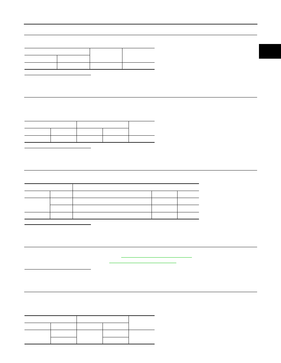
CHECK APP SENSOR 2 POWER SUPPLY CIRCUIT-I
Check the voltage between APP sensor harness connector and ground.
Is the inspection result normal?
YES
>> GO TO 7.
NO
>> GO TO 4.
4.
CHECK APP SENSOR 2 POWER SUPPLY CIRCUIT-II
1.
Turn ignition switch OFF.
2.
Disconnect ECM harness connector.
3.
Check the continuity between APP sensor harness connector and ECM harness connector.
Is the inspection result normal?
YES
>> GO TO 5.
NO
>> Repair open circuit or short to ground or shot to power in harness or connectors.
5.
CHECK SENSOR POWER SUPPLY CIRCUIT
Check harness for short to power and short to ground, between the following terminals.
Is the inspection result normal?
YES
>> GO TO 6.
NO
>> Repair short to ground or short to power in harness or connectors.
6.
CHECK COMPONENTS
Check the following.
• Crankshaft position sensor (POS) (Refer to
EC-428, "Component Inspection"
• Refrigerant pressure sensor (Refer to
.)
Is the inspection result normal?
YES
>> GO TO 9.
NO
>> Replace malfunctioning component.
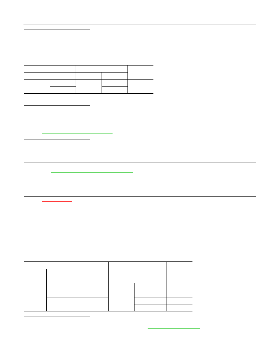
7.
CHECK APP SENSOR GROUND CIRCUIT FOR OPEN AND SHORT
1.
Turn ignition switch OFF.
2.
Disconnect ECM harness connector.
3.
Check the continuity between APP sensor harness connector and ECM harness connector as follows.
4.
Also check harness for short to ground and short to power.
APP sensor
Ground
Voltage
Connector
Terminal
M206
5
Ground
Approx. 5 V
APP sensor
ECM
Continuity
Connector
Terminal
Connector
Terminal
M206
5
E16
102
Existed
ECM
Sensor
Connector
Terminal
Item
Connector
Terminal
F8
74
Refrigerant pressure sensor
E49
3
75
CKP sensor (POS)
F20
1
E16
102
APP sensor
M206
5
APP sensor
ECM
Continuity
Connector
Terminal
Connector
Terminal
M206
1
E16
104
Existed
2
111
EC-474
< DTC/CIRCUIT DIAGNOSIS >
[HR12DE (TYPE 2)]
P2138 APP SENSOR
Is the inspection result normal?
YES
>> GO TO 8.
NO
>> Repair open circuit or short to ground or shot to power in harness or connectors.
8.
CHECK APP SENSOR INPUT SIGNAL CIRCUIT FOR OPEN AND SHORT
1.
Check the continuity between APP sensor harness connector and ECM harness connector as follows.
2.
Also check harness for short to ground and short to power.
Is the inspection result normal?
YES
>> GO TO 9.
NO
>> Repair open circuit or short to ground or shot to power in harness or connectors.
9.
CHECK APP SENSOR
EC-474, "Component Inspection"
Is the inspection result normal?
YES
>> GO TO 11.
NO
>> GO TO 10.
10.
REPLACE ACCELERATOR PEDAL ASSEMBLY
1.
Replace accelerator pedal assembly.
2.
EC-475, "Special Repair Requirement"
>> INSPECTION END
11.
CHECK INTERMITTENT INCIDENT
Refer to
XX-XX, "*****"
.
>> INSPECTION END
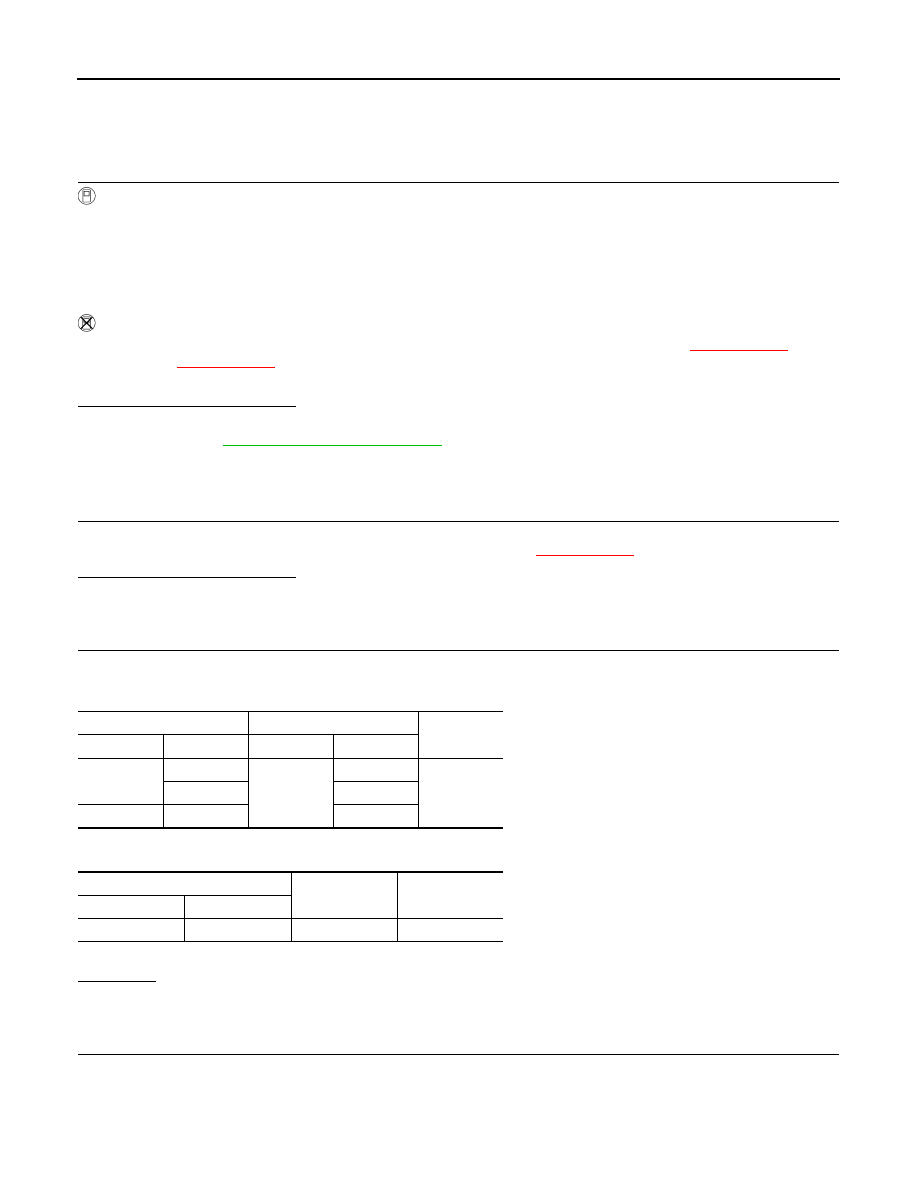
Component Inspection
INFOID:0000000006037399
1.
CHECK ACCELERATOR PEDAL POSITION SENSOR
1.
Reconnect all harness connectors disconnected.
2.
Turn ignition switch ON.
3.
Check the voltage between ECM harness connector and ground.
Is the inspection result normal?
YES
>> INSPECTION END
NO
>> Replace accelerator pedal assembly. Refer to
APP sensor
ECM
Continuity
Connector
Terminal
Connector
Terminal
M206
3
E16
110
Existed
6
103
ECM
Condition
Voltage
Connector
+
−
Terminal
Terminal
E16
110
(APP sensor 1 signal)
111
Accelerator
pedal
Fully released
0.6 - 0.9 V
Fully depressed
3.9 - 4.7 V
103
(APP sensor 2 signal)
104
Fully released
0.3 - 0.6 V
Fully depressed
1.95 - 2.4 V

P2138 APP SENSOR
EC-475
< DTC/CIRCUIT DIAGNOSIS >
[HR12DE (TYPE 2)]
C
D
E
F
G
H
I
J
K
L
M
A
EC
N
P
O
Special Repair Requirement
INFOID:0000000006037400
1.
PERFORM ACCELERATOR PEDAL RELEASED POSITION LEARNING
>> GO TO 2.
2.
PERFORM THROTTLE VALVE CLOSED POSITION LEARNING
>> GO TO 3.
3.
PERFORM IDLE AIR VOLUME LEARNING
>> END
EC-476
< DTC/CIRCUIT DIAGNOSIS >
[HR12DE (TYPE 2)]
COOLING FAN
COOLING FAN
Component Function Check
INFOID:0000000006037456
1.
CHECK COOLING FAN FUNCTION
With CONSULT-III
1.
Turn ignition switch ON.
2.
Perform “COOLING FAN” in “ACTIVE TEST” mode with CONSULT-III.
3.
Touch “LOW” and “HI” on the CONSULT-III screen.
4.
Check that cooling fan operates.
NOTE:
The cooling fan operates at high speeds even when “LOW” is selected in CONSULT-III “ACTIVE TEST”.
Without CONSULT-III
1.
Perform IPDM E/R auto active test and check cooling fan motor operation. Refer to
XX-XX, "*****"
(WITH
I-KEY) or
XX-XX, "*****"
(WITHOUT I-KEY).
2.
Check that cooling fan operates.
Is the inspection result normal?
YES
>> INSPECTION END
NO
>> Refer to
.
Diagnosis Procedure
INFOID:0000000006037457
1.
CHECK GROUND CONNECTION
1.
Turn ignition switch OFF.
2.
Check ground connection E38. Refer to Ground Inspection in
XX-XX, "*****"
.
Is the inspection result normal?
YES
>> GO TO 2.
NO
>> Repair or replace ground connection.
2.
CHECK COOLING FAN MOTOR CIRCUIT
1.
Disconnect cooling fan motor harness connector.
2.
Check the continuity between IPDM E/R harness connector and cooling fan motor harness connector.
3.
Check the continuity between cooling fan motor harness connector and ground.
4.
Also check harness for short to ground and short to power.
YES or NO
YES
>> GO TO 4.
NO
>> GO TO 3.
3.
DETECT MALFUNCTIONING PART
Check the following.
• Harness for open or short between cooling fan motor and IPDM E/R
• Harness for open or short between cooling fan motor and ground
IPDM E/R
Cooling fan motor
Continuity
Connector
Terminal
Connector
Terminal
E10
5
E62
1
Existed
7
2
E11
10
3
Cooling fan motor
Ground
Continuity
Connector
Terminal
E62
4
Ground
Existed
Нет комментариевНе стесняйтесь поделиться с нами вашим ценным мнением.
Текст