Nissan March K13. Manual — part 378
HAC-46
< DTC/CIRCUIT DIAGNOSIS >
[AUTOMATIC AIR CONDITIONER]
IN-VEHICLE SENSOR
Is the inspection result normal?
YES
>> Replace the A/C auto amp.
NO
>> Repair the harnesses or connectors.
Component Inspection
INFOID:0000000006024028
1.
CHECK IN-VEHICLE SENSOR
1.
Turn the ignition switch OFF.
2.
Remove the in-vehicle sensor. Refer to
XX-XX, "*****"
.
3.
Check the resistance between the in-vehicle sensor terminals. Refer to the applicable table for the normal
value.
Is the inspection result normal?
YES
>> INSPECTION END
NO
>> Replace the in-vehicle sensor.
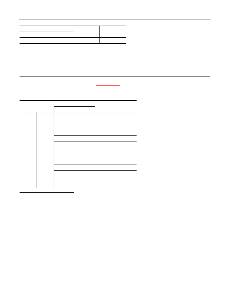
In-vehicle sensor
—
Continuity
Connector
Terminal
M41
1
Ground
Not existed
Terminal
Condition
Resistance: k
Ω
Temperature:
°
C (
°
F)
1
2
−
15 (5)
12.73
−
10 (14)
9.92
−
5 (23)
7.80
0 (32)
6.19
5 (41)
4.95
10 (50)
3.99
15 (59)
3.24
20 (68)
2.65
25 (77)
2.19
30 (86)
1.81
35 (95)
1.51
40 (104)
1.27
45 (113)
1.07
INTAKE SENSOR
HAC-47
< DTC/CIRCUIT DIAGNOSIS >
[AUTOMATIC AIR CONDITIONER]
C
D
E
F
G
H
J
K
L
M
A
B
HAC
N
O
P
INTAKE SENSOR
Diagnosis Procedure
INFOID:0000000006024030
1.
CHECK INTAKE SENSOR POWER SUPPLY CIRCUIT
1.
Turn the ignition switch OFF.
2.
Disconnect the intake sensor connector.
3.
Turn the ignition switch ON.
4.
Check voltage between intake sensor harness connector and the ground.
Is the inspection result normal?
YES
>> GO TO 2.
NO
>> GO TO 4.
2.
CHECK INTAKE SENSOR GROUND CIRCUIT CONTINUITY
1.
Turn the ignition switch OFF.
2.
Disconnect the A/C auto amp. connector.
3.
Check continuity between intake sensor harness connector and A/C auto amp. harness connector.
Is the inspection result normal?
YES
>> GO TO 3.
NO
>> Repair the harnesses or connectors.
3.
CHECK INTAKE SENSOR
Check the intake sensor components. Refer to
HAC-48, "Component Inspection"
Is the inspection result normal?
YES
>> INSPECTION END
NO
>> Replace the intake sensor.
4.
CHECK INTAKE SENSOR OPEN CIRCUIT
1.
Turn the ignition switch OFF.
2.
Disconnect the A/C auto amp. connector.
3.
Check continuity between intake sensor harness connector and A/C auto amp. harness connector.
Is the inspection result normal?
YES
>> GO TO 5.
NO
>> Repair the harnesses or connectors.
5.
CHECK INTAKE SENSOR SHORT CIRCUIT
Check continuity between intake sensor harness connector and the ground.
(+)
(
−
)
Voltage
(Approx.)
Intake sensor
—
Connector
Terminal
M42
1
Ground
5 V
Intake sensor
A/C auto amp.
Continuity
Connector
Terminal
Connector
Terminal
M42
2
M50
40
Existed
Intake sensor
A/C auto amp.
Continuity
Connector
Terminal
Connector
Terminal
M42
1
M50
37
Existed
HAC-48
< DTC/CIRCUIT DIAGNOSIS >
[AUTOMATIC AIR CONDITIONER]
INTAKE SENSOR
Is the inspection result normal?
YES
>> Replace the A/C auto amp.
NO
>> Repair the harnesses or connectors.
Component Inspection
INFOID:0000000006024031
1.
CHECK INTAKE SENSOR
1.
Turn the ignition switch OFF.
2.
Disconnect the intake sensor connector.
3.
Check the resistance between the intake sensor terminals. Refer to the applicable table for the normal
value.
Is the inspection result normal?
YES
>> INSPECTION END
NO
>> Replace the intake sensor.
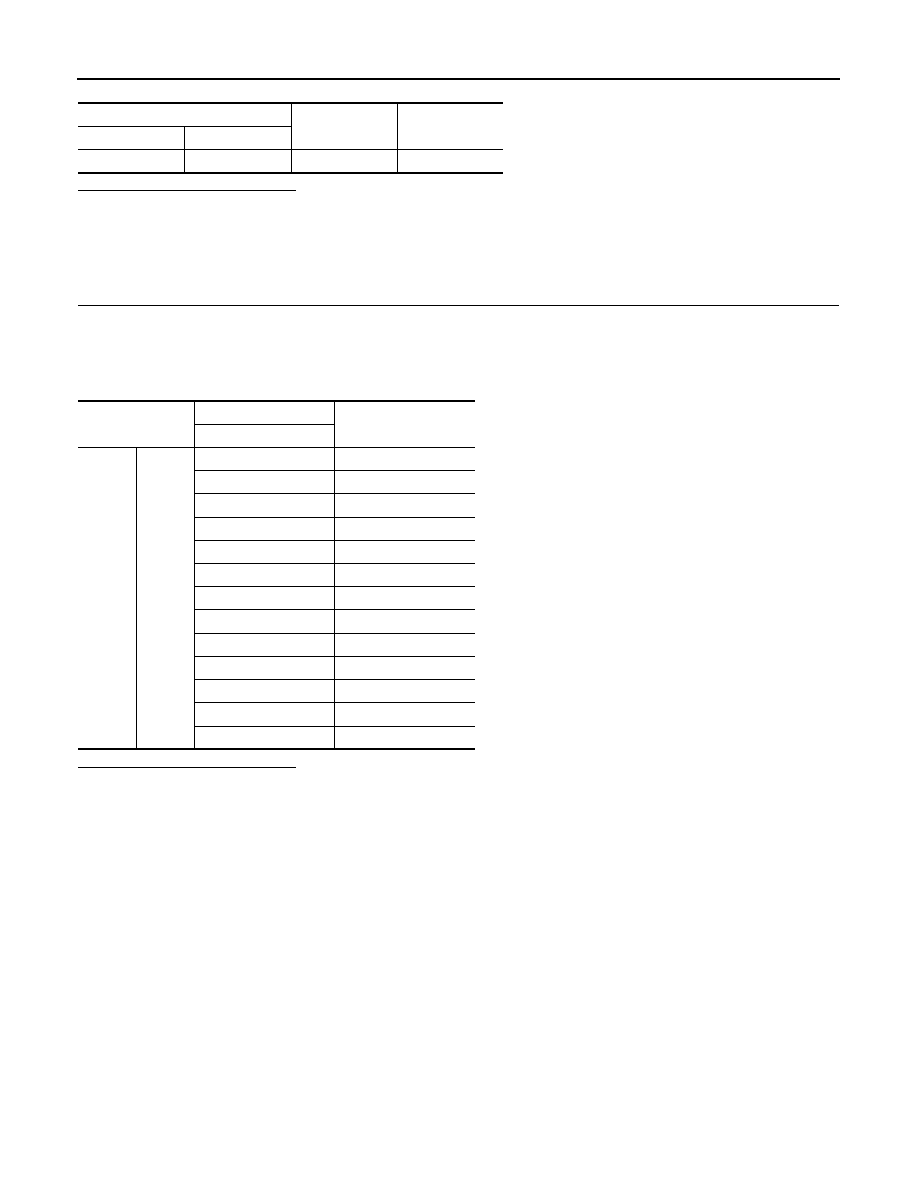
Intake sensor
—
Continuity
Connector
Terminal
M42
1
Ground
Not existed.
Terminal
Condition
Resistance: k
Ω
Temperature:
°
C (
°
F)
1
2
−
15 (5)
12.34
−
10 (14)
9.62
−
5 (23)
7.56
0 (32)
6.00
5 (41)
4.80
10 (50)
3.87
15 (59)
3.15
20 (68)
2.57
25 (77)
2.12
30 (86)
1.76
35 (95)
1.47
40 (104)
1.23
45 (113)
1.04
SUNLOAD SENSOR
HAC-49
< DTC/CIRCUIT DIAGNOSIS >
[AUTOMATIC AIR CONDITIONER]
C
D
E
F
G
H
J
K
L
M
A
B
HAC
N
O
P
SUNLOAD SENSOR
Diagnosis Procedure
INFOID:0000000006024033
1.
CHECK SUNLOAD SENSOR POWER SUPPLY CIRCUIT
1.
Turn the ignition switch OFF.
2.
Disconnect the sunload sensor connector.
3.
Turn the ignition switch ON.
4.
Check voltage between sunload sensor harness connector and the ground.
Is the inspection result normal?
YES
>> GO TO 2.
NO
>> GO TO 4.
2.
CHECK SUNLOAD SENSOR GROUND CIRCUIT CONTINUITY
1.
Turn the ignition switch OFF.
2.
Disconnect the A/C auto amp. connector.
3.
Check continuity between sunload sensor harness connector and A/C auto amp. harness connector.
Is the inspection result normal?
YES
>> GO TO 3.
NO
>> Repair the harnesses or connectors.
3.
CHECK SUNLOAD SENSOR
1.
Connect the sunload sensor connector.
2.
Connect the A/C auto amp. connector.
3.
Check the sunload sensor components. Refer to
HAC-50, "Component Inspection"
Is the inspection result normal?
YES
>> INSPECTION END
NO
>> Replace the sunload sensor.
4.
CHECK SUNLOAD SENSOR OPEN CIRCUIT
1.
Turn the ignition switch OFF.
2.
Disconnect the A/C auto amp. connector.
3.
Check continuity between sunload sensor harness connector and A/C auto amp. harness connector.
Is the inspection result normal?
YES
>> GO TO 5.
NO
>> Repair the harnesses or connectors.
5.
CHECK SUNLOAD SENSOR SHORT CIRCUIT
Check continuity between sunload sensor harness connector and the ground.
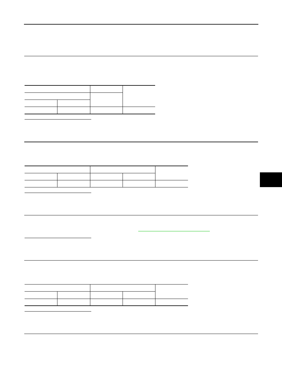
(+)
(
−
)
Voltage
(Approx.)
Sunload sensor
—
Connector
Terminal
M74
1
Ground
5 V
Sunload sensor
A/C auto amp.
Continuity
Connector
Terminal
Connector
Terminal
M74
2
M50
40
Existed
Sunload sensor
A/C auto amp.
Continuity
Connector
Terminal
Connector
Terminal
M74
1
M50
18
Existed
Нет комментариевНе стесняйтесь поделиться с нами вашим ценным мнением.
Текст