Nissan March K13. Manual — part 224
ECM
EC-357
< ECU DIAGNOSIS INFORMATION >
[HR12DE (TYPE 2)]
C
D
E
F
G
H
I
J
K
L
M
A
EC
N
P
O
*: Accelerator pedal position sensor 2 signal and throttle position sensor 2 signal are converted by ECM inter-
nally. Thus, they differ from ECM terminals voltage signal.
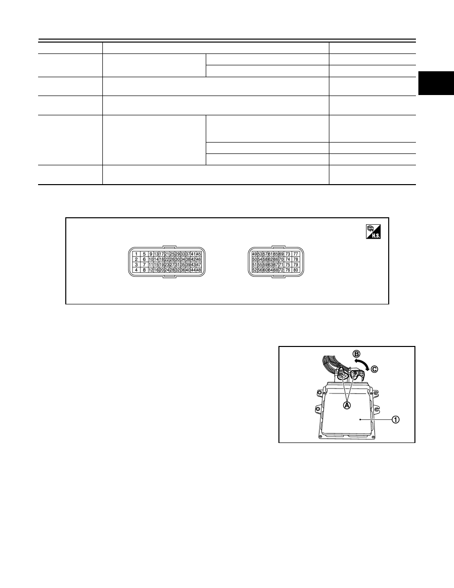
TERMINAL LAYOUT
PHYSICAL VALUES
NOTE:
• ECM is located in the engine room left side near battery.
• When disconnecting ECM harness connector (A), loosen (C) it with
levers as far as they will go as shown in the figure.
- ECM (1)
- Fasten (B)
• Connect a break-out box and harness adapter between the ECM
and ECM harness connector.
- Use extreme care not to touch 2 pins at one time.
- Data is for comparison and may not be exact.
• Specification data are reference values and are measured
between each terminals.
• Pulse signal is measured by CONSULT-III.
P/N POSI SW
• Ignition switch: ON
Shift lever: Neutral
On
Shift lever: Except above
Off
INT/A TEMP SE
• Ignition switch: ON
Indicates intake air tempera-
ture.
AC PRESS SEN
• Engine: Idle
• Both A/C switch and blower fan switch: ON (Compressor operates)
1.0 - 4.0 V
TURBO BST SEN
• Engine: After warming up
Ignition switch: ON
Engine stopped
4.5 V
Output voltage varies with at-
mospheric pressure.
Engine: Idle
1.3 - 1.5 V
Maintaining engine speed at 2,000 rpm
1.0 - 1.2V
O2 SEN HTR DTY
• Engine coolant temperature when engine started: More than 80
°
C (176
°
F)
• Engine speed: Below 3,600 rpm
Approx. 30%
Monitor Item
Condition
Values/Status
JSBIA0404ZZ
JSBIA0405ZZ
EC-358
< ECU DIAGNOSIS INFORMATION >
[HR12DE (TYPE 2)]
ECM
Terminal No.
Description
Condition
Value
(Approx.)
+
–
Signal name
Input/
Output
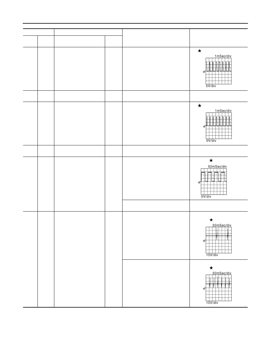
1
(L)
80
(B)
Throttle control motor
(Open)
Output
[Ignition switch: ON]
• Engine stopped
• Shift lever: D (A/T) or 1st (M/T)
• Accelerator pedal: Fully depressed
2 V
2
(SB)
80
(B)
Throttle control motor power
supply
Input
[Ignition switch: ON]
BATTERY VOLTAGE
(11 - 14 V)
3
(P)
80
(B)
Throttle control motor
(Close)
Output
[Ignition switch: ON]
• Engine stopped
• Shift lever: D (A/T) or 1st (M/T)
• Accelerator pedal: Fully released
2 V
4
(B)
—
ECM ground
—
—
—
5
(G)
80
(B)
Heated oxygen sensor 1
heater
Output
[Engine is running]
• Warm-up condition
• Idle speed
2.9 - 8.8 V
[Engine is running]
• Engine speed: Above 3,600 rpm
BATTERY VOLTAGE
(11 - 14 V)
6
(Y)
80
(B)
Fuel injector No. 1
Output
[Engine is running]
• Warm-up condition
• Idle speed
NOTE:
The pulse cycle changes depending
on rpm at idle
BATTERY VOLTAGE
(11 - 14 V)
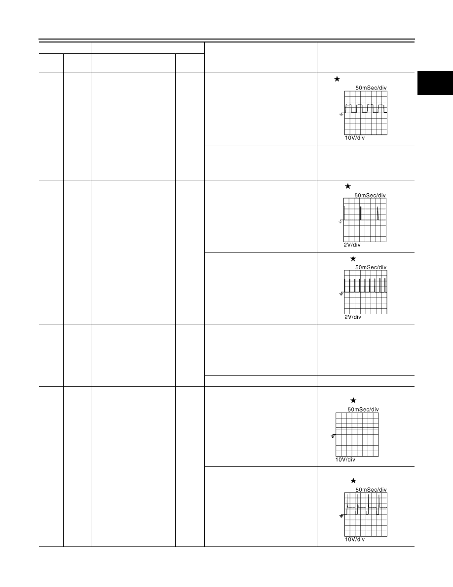
7
(O)
Fuel injector No. 2
8
(L)
Fuel injector No. 3
[Engine is running]
• Warm-up condition
• Engine speed: 2,000 rpm
BATTERY VOLTAGE
(11 - 14 V)
JMBIA0213GB
JMBIA0215GB
JMBIA0030GB
JMBIA0221GB
JMBIA0222GB
ECM
EC-359
< ECU DIAGNOSIS INFORMATION >
[HR12DE (TYPE 2)]
C
D
E
F
G
H
I
J
K
L
M
A
EC
N
P
O
9
(G)
80
(B)
Heated oxygen sensor 2
heater
Output
[Engine is running]
• Engine speed: Below 3,900 rpm af-
ter the following conditions are met
- Engine: after warming up
- Keeping the engine speed between
3,500 and 4,000 rpm for 1 minute
and at idle for 1 minute under no
load
10 V
[Ignition switch: ON]
• Engine stopped
[Engine is running]
• Engine speed: Above 3,900 rpm
BATTERY VOLTAGE
(11 - 14 V)
10
(LG)
80
(B)
Ignition signal No. 2
Output
[Engine is running]
• Warm-up condition
• Idle speed
NOTE:
The pulse cycle changes depending
on rpm at idle
0 - 0.3 V
14
(R)
Ignition signal No. 1
15
(SB)
Ignition signal No. 3
[Engine is running]
• Warm-up condition
• Engine speed: 2,500 rpm
0.2 - 0.5 V
11
(Y)
80
(B)
Throttle control motor relay
Output
[Ignition switch: ON
→
OFF]
0 - 1.0 V
↓
BATTERY VOLTAGE
(11 - 14 V)
↓
0 V
[Ignition switch: ON]
0 - 1.0 V
13
(P)
80
(B)
EVAP canister purge volume
control solenoid valve
Output
[Engine is running]
• Idle speed
BATTERY VOLTAGE
(11 - 14 V)
[Engine is running]
• Engine speed: About 2,000 rpm
(More than 100 seconds after start-
ing engine.)
BATTERY VOLTAGE
(11 - 14 V)
Terminal No.
Description
Condition
Value
(Approx.)
+
–
Signal name
Input/
Output
JMBIA0214GB
JMBIA0219GB
JMBIA0220GB
JMBIA0039GB
JMBIA0216GB

EC-360
< ECU DIAGNOSIS INFORMATION >
[HR12DE (TYPE 2)]
ECM
16
(GR)
80
(B)
Fuel pump relay
Output
[Ignition switch: ON]
• For 1 second after turning ignition
switch ON
[Engine is running]
0 - 1.0 V
[Ignition switch: ON]
• More than 1 second after turning ig-
nition switch ON
BATTERY VOLTAGE
(11 - 14 V)
18
(P)
80
(B)
ECM relay
(Self shut-off)
Output
[Engine is running]
[Ignition switch: OFF]
• A few seconds after turning ignition
switch OFF
0 - 1.0 V
[Ignition switch: OFF]
• More than a few seconds after turn-
ing ignition switch OFF
BATTERY VOLTAGE
(11 - 14 V)
20
(Y)
—
Sensor ground
(Throttle position sensor)
—
—
—
21
(LG)
20
(Y)
Throttle position sensor 1
Input
[Ignition switch: ON]
• Engine stopped
• Shift lever: D (A/T) or 1st (M/T)
• Accelerator pedal: Fully released
More than 0.36 V
[Ignition switch: ON]
• Engine stopped
• Shift lever: D (A/T) or 1st (M/T)
• Accelerator pedal: Fully depressed
Less than 4.75 V
22
(O)
20
(Y)
Throttle position sensor 2
Input
[Ignition switch: ON]
• Engine stopped
• Shift lever: D (A/T) or 1st (M/T)
• Accelerator pedal: Fully released
Less than 4.75 V
[Ignition switch: ON]
• Engine stopped
• Shift lever: D (A/T) or 1st (M/T)
• Accelerator pedal: Fully depressed
More than 0.36 V
23
—
—
Sensor ground
(Knock sensor shield circuit)
—
—
—
24
(B)
—
Sensor ground
(Engine coolant temperature
sensor)
—
—
—
25
(W)
23
—
Knock sensor
Input
[Engine is running]
• Idle speed
2.5 V
26
(P)
24
(B)
Engine coolant temperature
sensor
Input
[Engine is running]
0 - 4.8 V
Output voltage varies with engine
coolant temperature.
27
(BR)
—
Sensor ground
(Refrigerant pressure sen-
sor)
—
—
—
28
(BR)
—
Sensor ground
[Manifold absolute pressure
(MAP) sensor]
—
—
—
29
(GR)
27
(BR)
Refrigerant pressure sensor
Input
[Engine is running]
• Warm-up condition
• Both A/C switch and blower fan
switch: ON (Compressor operates)
1.0 - 4.0 V
Terminal No.
Description
Condition
Value
(Approx.)
+
–
Signal name
Input/
Output
Нет комментариевНе стесняйтесь поделиться с нами вашим ценным мнением.
Текст