Nissan March K13. Manual — part 220
SYSTEM
EC-341
< SYSTEM DESCRIPTION >
[HR12DE (TYPE 2)]
C
D
E
F
G
H
I
J
K
L
M
A
EC
N
P
O
*1: ECM determines the start signal status by the signals of engine speed and battery voltage.
*2: This signal is sent to the ECM through CAN communication line.
SYSTEM DESCRIPTION
Firing order: 1 - 2 - 3
The ignition timing is controlled by the ECM to maintain the best air-fuel ratio for every running condition of the
engine. The ignition timing data is stored in the ECM.
The ECM receives information such as the injection pulse width and camshaft position sensor (PHASE) sig-
nal. Computing this information, ignition signals are transmitted to the power transistor.
During the following conditions, the ignition timing is revised by the ECM according to the other data stored in
the ECM.
• At starting
• During warm-up
• At idle
• At low battery voltage
• During acceleration
The knock sensor retard system is designed only for emergencies. The basic ignition timing is programmed
within the anti-knocking zone, if recommended fuel is used under dry conditions. The retard system does not
operate under normal driving conditions. If engine knocking occurs, the knock sensor monitors the condition.
The signal is transmitted to the ECM. The ECM retards the ignition timing to eliminate the knocking condition.
AIR CONDITIONING CUT CONTROL
Sensor
Input signal to ECM
ECM function
Actuator
Crankshaft position sensor (POS)
Engine speed
*1
Piston position
Ignition timing
control
Ignition coil (with power tran-
sistor)
Camshaft position sensor (PHASE)
Manifold absolute pressure (MAP) sensor
Amount of intake air
Engine coolant temperature sensor
Engine coolant temperature
Throttle position sensor
Throttle position
Accelerator pedal position sensor
Accelerator pedal position
Park/neutral position (PNP) switch (M/T mod-
els)
PNP signal
Transmission range switch (A/T models)
Battery
Battery voltage
*1
Knock sensor
Engine knocking
Combination meter
Vehicle speed signal
*2

EC-342
< SYSTEM DESCRIPTION >
[HR12DE (TYPE 2)]
SYSTEM
AIR CONDITIONING CUT CONTROL : System Diagram
INFOID:0000000006036819
AIR CONDITIONING CUT CONTROL : System Description
INFOID:0000000006036820
INPUT/OUTPUT SIGNAL CHART
*1: ECM determines the start signal status by the signals of engine speed and battery voltage.
*2: This signal is sent to the ECM through CAN communication line.
SYSTEM DESCRIPTION
This system improves engine operation when the air conditioner is used.
Under the following conditions, the air conditioner is turned off.
• When the accelerator pedal is fully depressed.
• When cranking the engine.
• At high engine speeds.
• When the engine coolant temperature becomes excessively high.
• When operating power steering during low engine speed or low vehicle speed.
• When engine speed is excessively low.
• When refrigerant pressure is excessively low or high.
JSBIA0320GB
Sensor
Input signal to ECM
ECM function
Actuator
Crankshaft position sensor (POS)
Camshaft position sensor (PHASE)
Engine speed
*1
A/C compressor
repuest signal
IPDM E/R
↓
Air conditioner relay
↓
Compressor
Engine coolant temperature sensor
Engine coolant temperature
Accelerator pedal position sensor
Accelerator pedal position
Battery
Battery voltage
*1
Refrigerant pressure sensor
Refrigerant pressure
EPS control unit
EPS operation signal
*2
Combination meter
Vehicle speed signal
*2
BCM
A/C ON signal
*2
Blower fan ON signal
SYSTEM
EC-343
< SYSTEM DESCRIPTION >
[HR12DE (TYPE 2)]
C
D
E
F
G
H
I
J
K
L
M
A
EC
N
P
O
CAN COMMUNICATION
CAN COMMUNICATION : System Description
INFOID:0000000006036821
CAN (Controller Area Network) is a serial communication line for real time application. It is an on-vehicle mul-
tiplex communication line with high data communication speed and excellent error detection ability. Many elec-
tronic control units are equipped onto a vehicle, and each control unit shares information and links with other
control units during operation (not independent). In CAN communication, control units are connected with 2
communication lines (CAN H line, CAN L line) allowing a high rate of information transmission with less wiring.
Each control unit transmits/receives data but selectively reads required data only.
Refer to
LAN-23, "CAN COMMUNICATION SYSTEM : CAN Communication Signal Chart"
munication for detail.
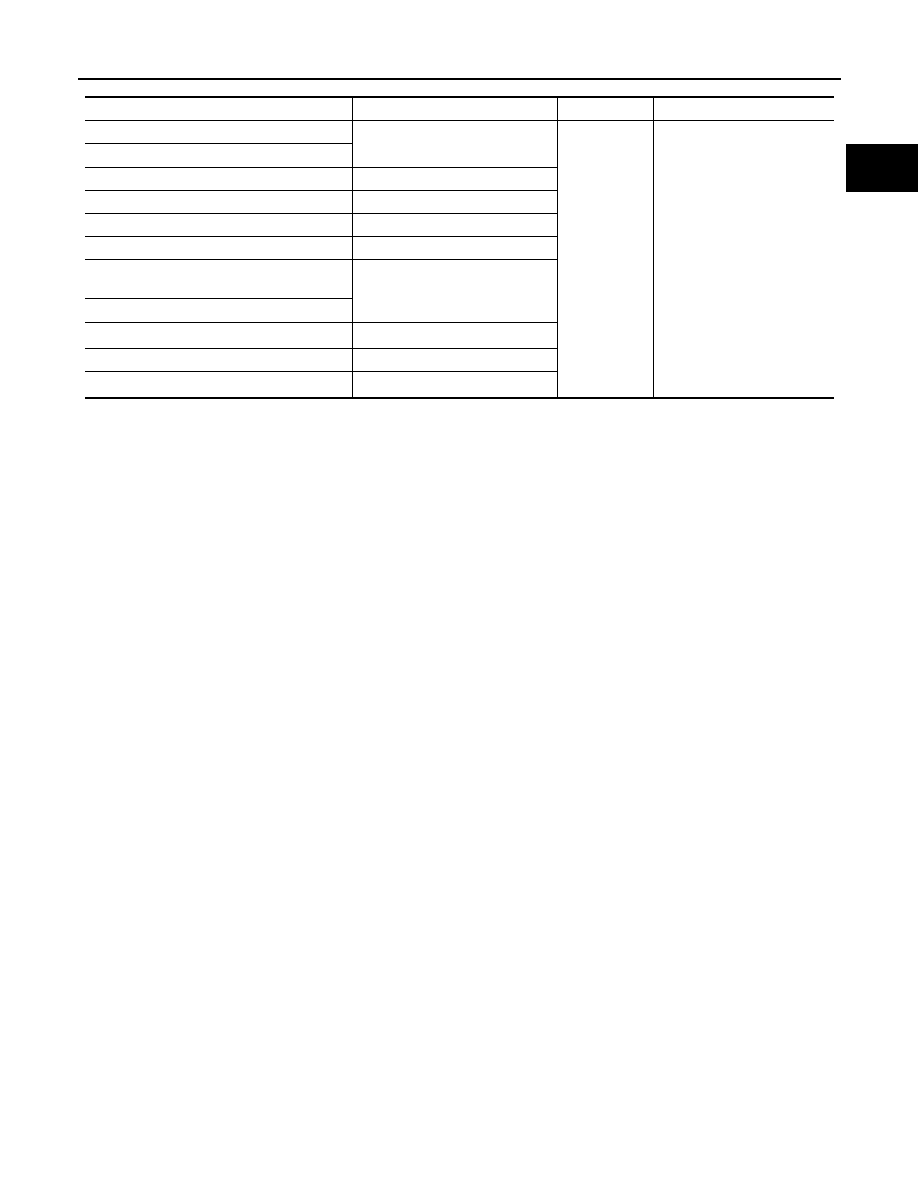
COOLING FAN CONTROL
COOLING FAN CONTROL : System Diagram
INFOID:0000000006036824
COOLING FAN CONTROL : System Description
INFOID:0000000006036825
INPUT/OUTPUT SIGNAL CHART
*1: ECM determines the start signal status by the signals of engine speed and battery voltage.
*2: This signal is sent to ECM through CAN communication line.
SYSTEM DESCRIPTION
ECM controls cooling fan speed corresponding to vehicle speed, engine coolant temperature, refrigerant pres-
sure, air conditioner ON signal. Then control system has 2-step control [HIGH/OFF].
JSBIA0321GB
Sensor
Input signal to ECM
ECM function
Actuator
Crankshaft position sensor (POS)
Camshaft position sensor (PHASE)
Engine speed
*1
Cooling fan
speed request
signal
IPDM E/R
↓
Cooling fan relay
↓
Cooling fan motor
Engine coolant temperature sensor
Engine coolant temperature
Refrigerant pressure sensor
Refrigerant pressure
Battery
Battery voltage
*1
Combination meter
Vehicle speed signal
*2
BCM
A/C ON signal
*2
Blower fan ON signal
EC-344
< SYSTEM DESCRIPTION >
[HR12DE (TYPE 2)]
SYSTEM
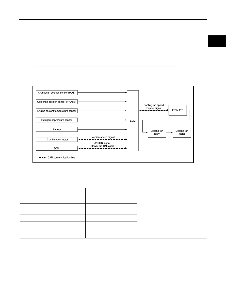
Cooling Fan Operation
Cooling Fan Relay Operation
The ECM controls cooling fan relays through CAN communication line.
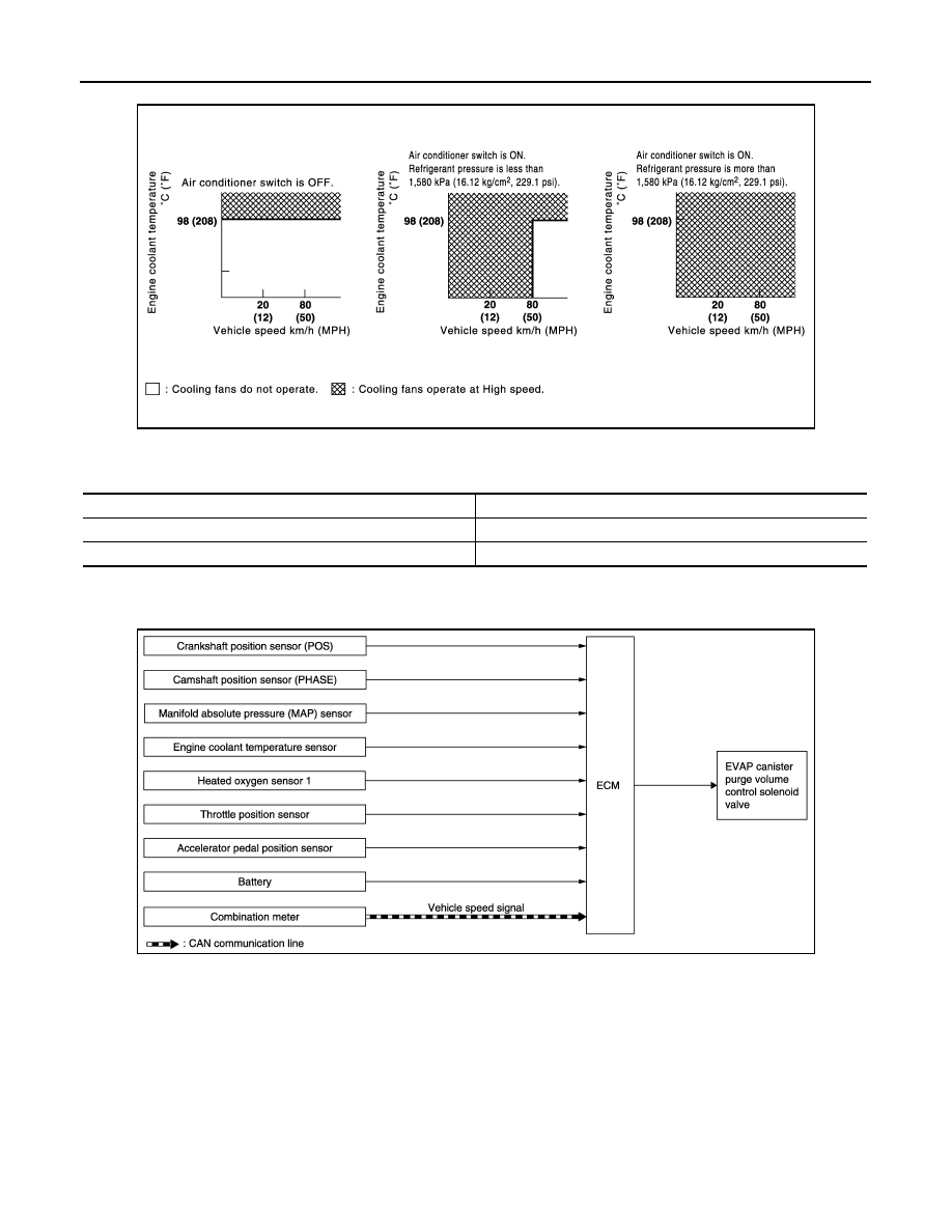
EVAPORATIVE EMISSION SYSTEM
EVAPORATIVE EMISSION SYSTEM : System Diagram
INFOID:0000000006036828
EVAPORATIVE EMISSION SYSTEM : System Description
INFOID:0000000006036829
INPUT/OUTPUT SIGNAL CHART
JSBIA0415GB
Cooling fan speed
Cooling fan relay
Stop (OFF)
OFF
High (HI)
ON
JSBIA0438GB
Нет комментариевНе стесняйтесь поделиться с нами вашим ценным мнением.
Текст