Nissan March K13. Manual — part 53
CHG-26
< REMOVAL AND INSTALLATION >
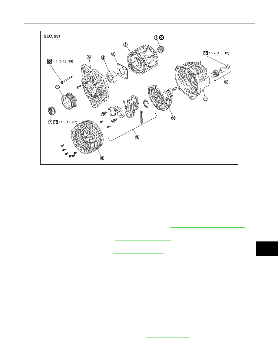
ALTERNATOR
Type: 2607689
JMMIA0406GB
1.
Rotor assembly
2.
Retainer
3.
Front bearing
4.
Front bracket assembly
5.
Pulley
6.
Pulley nut
7.
Stator assembly
8.
Rear bearing
9.
Rear bracket assembly
10. Circuit board assembly
11.
Regulator assembly
12. Stud bolt
13. Cover
Refer to
for symbols in the figure.
CHG
ALTERNATOR
CHG-27
< REMOVAL AND INSTALLATION >
C
D
E
F
G
H
I
J
K
L
B
A
O
P
N
Type: A005TL0191
Removal and Installation
INFOID:0000000006057265
REMOVAL
1.
Disconnect the battery cable from the negative terminal. Refer to
PG-143, "Removal and Installation"
2.
Remove drive belt. Refer to
EM-19, "Removal and Installation"
.
3.
Remove condenser side seal. Refer to
4.
Remove A/C compressor mounting bolts, and then A/C compressor
を
radiator core suppurt lower
の上に仮
置きする
(with A/C models)
。
Refer to
.
5.
Disconnect alternator connector.
6.
Remove terminal B nut and disconnect terminal B harness.
7.
Remove alternator mounting bolt upper.
8.
Remove alternator mounting bolt lower.
9.
Alternator
を車両横側から取り外す。
INSTALLATION
Install in the reverse order of removal.
CAUTION:
• Temporarily tighten the alternator bolts in order from the lower to the upper, and then tighten them in
order from the upper to the lower.
• For the alternator, the front side (pulley side) surface is the reference surface. Fit the reference sur-
face to the alternator mounting part, and then tighten the bolts.
• Be careful to tighten terminal B nut carefully.
• Install alternator, and check tension of belt. Refer to
JMMIA0389GB
1.
Rear bearing
2.
Rotor assembly
3.
Retainer
4.
Front bearing
5.
Front bracket assembly
6.
Pulley
7.
Pulley nut
8.
Stator assembly
9.
IC voltage regulator assembly
10. Diode assembly
11.
Rear bracket assembly
12. Terminal set
Refer to
CHG-28
< REMOVAL AND INSTALLATION >
ALTERNATOR
Disassembly and Assembly
INFOID:0000000006057266
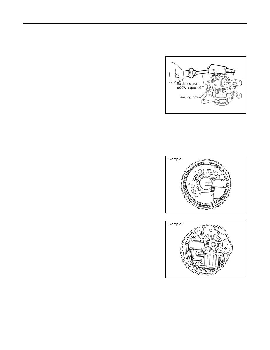
DISASSEMBLY
Rear Cover
NOTE:
Rear cover may be hard to remove because a ring is used to lock
outer race of rear bearing. To facilitate removal of rear cover, heat
only the bearing box section until the temperature increases to
approximately 30
°
C (86
°
F) with a soldering iron (200W capacity).
CAUTION:
Never use a heat gun, as if can damage diode assembly.
ASSEMBLY
Rear Bearing
CAUTION:
• Never reuse rear bearing. Replace with a new one.
• Never lubricate rear bearing outer race.
Rear Cover Installation
1.
Fit brush assembly, diode assembly, regulator assembly and
stator.
2.
Push brushed up with fingers and install them to rotor.
NOTE:
Take care not damage slip ring sliding surface.
Inspection
INFOID:0000000006057267
INSPECTION
Rotor Check
SEL032Z
SKIB4529E
SKIB4530E

CHG
ALTERNATOR
CHG-29
< REMOVAL AND INSTALLATION >
C
D
E
F
G
H
I
J
K
L
B
A
O
P
N
1.
Resistance test
• Replace the rotor if the measurement value is outside of the
specified range.
2.
Insulator test
• Replace the rotor if continuity exists.
3.
Check slip ring for wear.
• Replace the rotor if the measurement value is outside of the specified range.
Brush Check
1.
Check smooth movement of brush.
• Check brush holder and clean if it is not smooth.
2.
Check brush for wear.
• Replace brush if it is worn down to the limit line.
Stator Check
1.
Continuity test
• Replace the stator if continuity does not exist.
2.
Ground test
• Replace the stator if continuity exists.
Resistance
: Refer to SDS
.
Slip ring minimum
outer diameter
: Refer to SDS
.
SKIB4525E
SKIB4526E
SKIB4527E
SKIB4528E
Нет комментариевНе стесняйтесь поделиться с нами вашим ценным мнением.
Текст