Nissan March K13. Manual — part 145
SYSTEM
EC-41
< SYSTEM DESCRIPTION >
[HR12DE (TYPE 1)]
C
D
E
F
G
H
I
J
K
L
M
A
EC
N
P
O
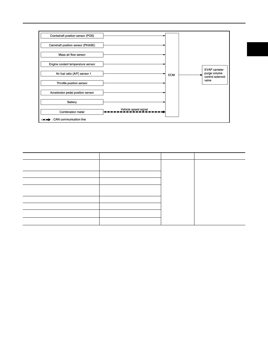
EVAPORATIVE EMISSION SYSTEM : System Diagram
INFOID:0000000005995411
EVAPORATIVE EMISSION SYSTEM : System Description
INFOID:0000000005995412
INPUT/OUTPUT SIGNAL CHART
*1: ECM determines the start signal status by the signals of engine speed and battery voltage.
*2: This signal is sent to the ECM through CAN communication line.
JSBIA0322GB
Sensor
Input signal to ECM
ECM function
Actuator
Crankshaft position sensor (POS)
Camshaft position sensor (PHASE)
Engine speed
*1
EVAP canister
purge flow control
EVAP canister purge volume
control solenoid valve
Mass air flow sensor
Amount of intake air
Engine coolant temperature sensor
Engine coolant temperature
Air fuel ratio (A/F) sensor 1
Density of oxygen in exhaust gas
(Mixture ratio feedback signal)
Throttle position sensor
Throttle position
Accelerator pedal position sensor
Accelerator pedal position
Battery
Battery voltage
*1
Combination meter
Vehicle speed signal
*2
EC-42
< SYSTEM DESCRIPTION >
[HR12DE (TYPE 1)]
SYSTEM
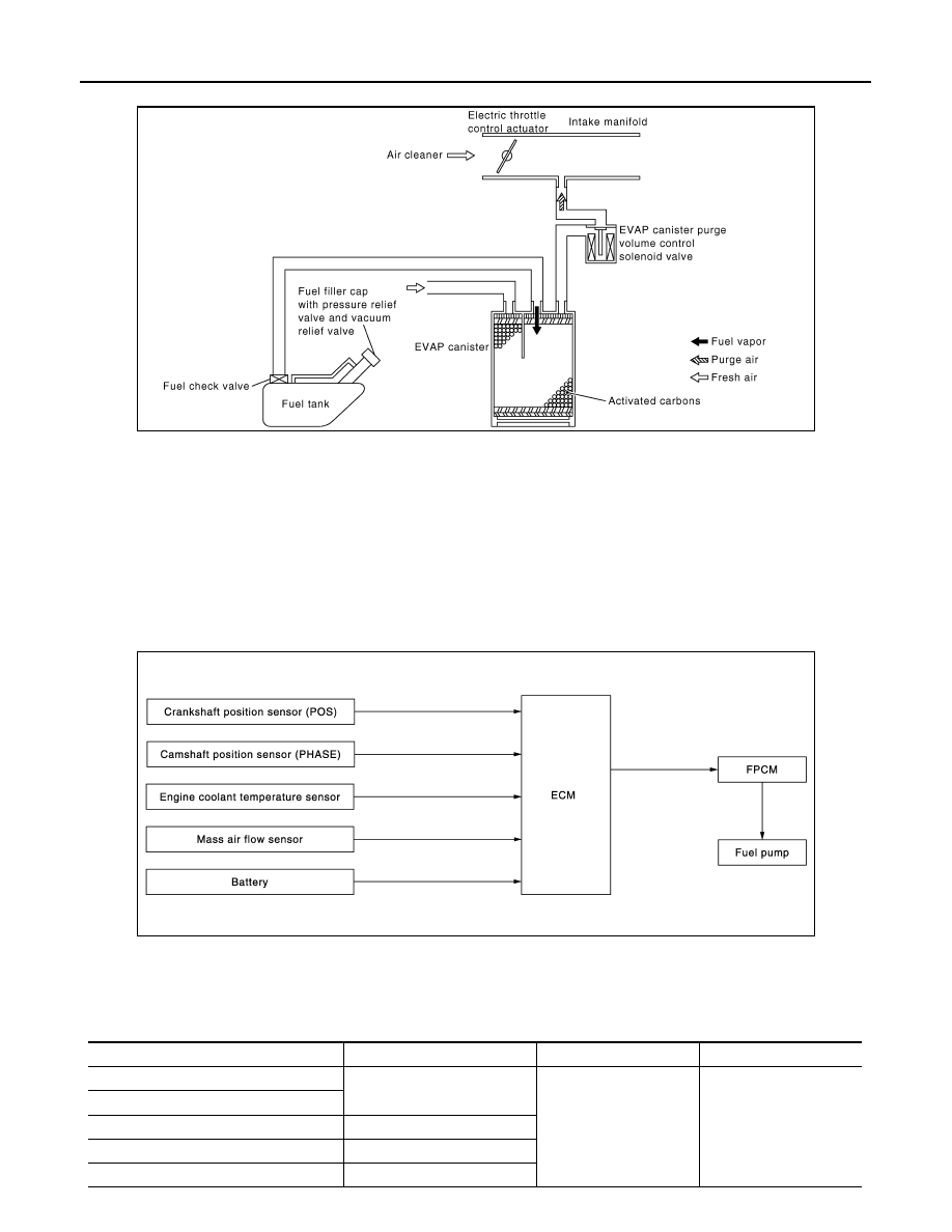
SYSTEM DESCRIPTION
The evaporative emission system is used to reduce hydrocarbons emitted into the atmosphere from the fuel
system. This reduction of hydrocarbons is accomplished by activated charcoals in the EVAP canister.
The fuel vapor in the sealed fuel tank is led into the EVAP canister which contains activated carbon and the
vapor is stored there when the engine is not operating or when refueling to the fuel tank.
The vapor in the EVAP canister is purged by the air through the purge line to the intake manifold when the
engine is operating. EVAP canister purge volume control solenoid valve is controlled by ECM. When the
engine operates, the flow rate of vapor controlled by EVAP canister purge volume control solenoid valve is
proportionally regulated as the air flow increases.
EVAP canister purge volume control solenoid valve also shuts off the vapor purge line during decelerating.
FUEL PUMP CONTROL MODULE (FPCM)
FUEL PUMP CONTROL MODULE (FPCM) : System Diagram
INFOID:0000000005995413
FUEL PUMP CONTROL MODULE (FPCM) : System Description
INFOID:0000000005995414
INPUT/OUTPUT SIGNAL CHART
PBIB3039E
JSBIA0366GB
Sensor
Input signal to ECM
ECM function
Actuator
Crankshaft position sensor (POS)
Engine speed*
Fuel pump control
FPCM
↓
Fuel pump
Camshaft position sensor (PHASE)
Engine coolant temperature sensor
Engine coolant temperature
Mass air flow sensor
Amount of intake air
Battery
Battery voltage*
SYSTEM
EC-43
< SYSTEM DESCRIPTION >
[HR12DE (TYPE 1)]
C
D
E
F
G
H
I
J
K
L
M
A
EC
N
P
O
*: ECM determines the start signal status by the signals of engine speed and battery voltage.
SYSTEM DESCRIPTION
The fuel pump control module (FPCM) controls the discharging volume of the fuel pump by the FPCM control
signals (Low/Mid/High) depending on driving conditions.
INTAKE VALVE TIMING CONTROL
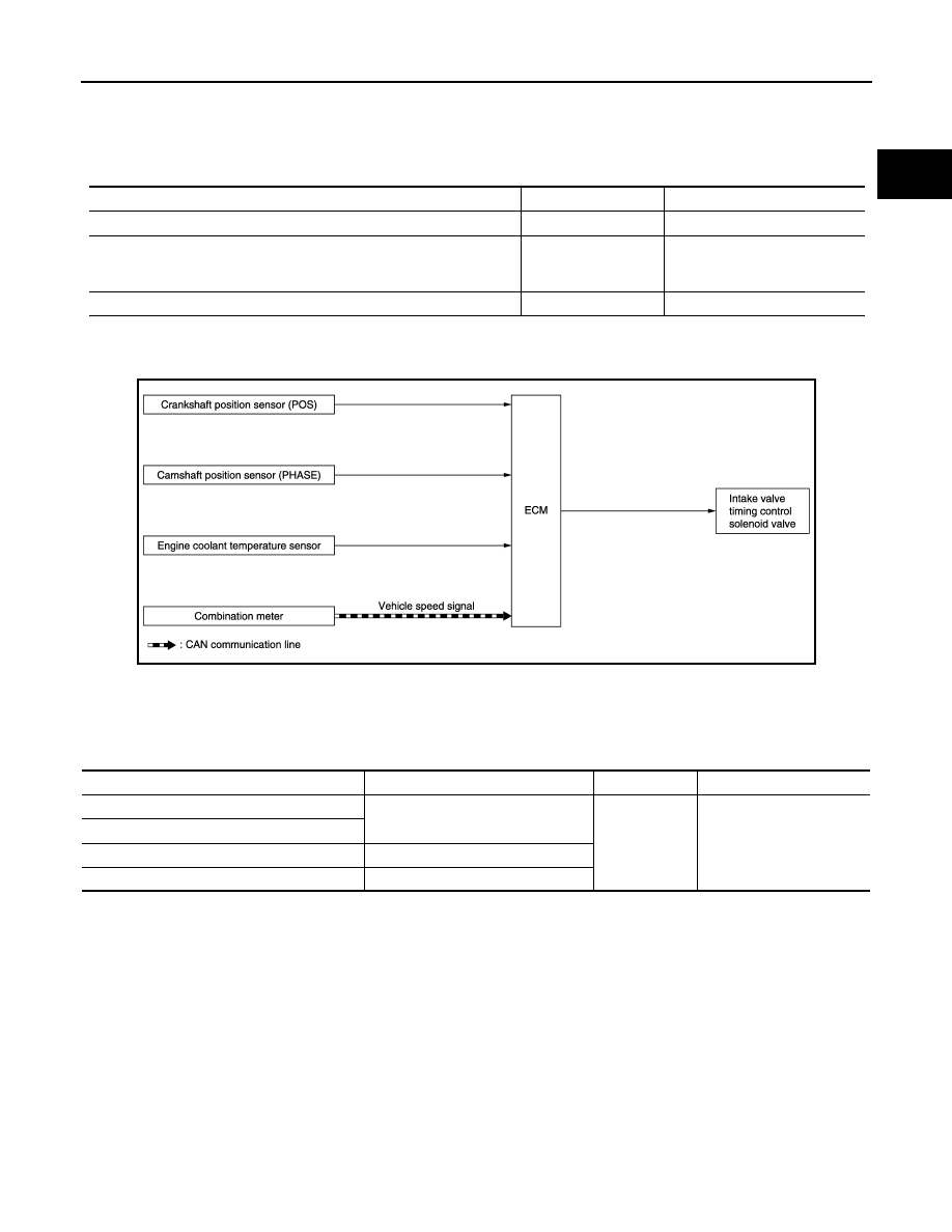
INTAKE VALVE TIMING CONTROL : System Diagram
INFOID:0000000005995415
INTAKE VALVE TIMING CONTROL : System Description
INFOID:0000000005995416
INPUT/OUTPUT SIGNAL CHART
*: This signal is sent to the ECM through CAN communication line.
Conditions
Amount of fuel flow
Supplied voltage
For 1 second after turning ignition switch ON
Low
Approximately 8.5 V
• Engine cranking
• Engine coolant temperature is below 10
°
C (50
°
F)
• Engine is running under high load and high speed conditions
High
Battery voltage
(11 - 14 V)
Except the above
Mid
Approximately 10 V
JSBIA0323GB
Sensor
Input signal to ECM
ECM function
Actuator
Crankshaft position sensor (POS)
Engine speed and piston position
Intake valve
timing control
Intake valve timing control
solenoid valve
Camshaft position sensor (PHASE)
Engine coolant temperature sensor
Engine coolant temperature
Combination meter
Vehicle speed signal*
EC-44
< SYSTEM DESCRIPTION >
[HR12DE (TYPE 1)]
SYSTEM
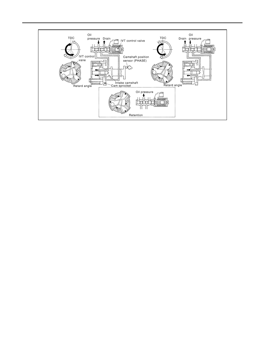
SYSTEM DESCRIPTION
This mechanism hydraulically controls cam phases continuously with the fixed operating angle of the intake
valve.
The ECM receives signals such as crankshaft position, camshaft position, engine speed, and engine coolant
temperature. Then, the ECM sends ON/OFF pulse duty signals to the intake valve timing (IVT) control sole-
noid valve depending on driving status. This makes it possible to control the shut/open timing of the intake
valve to increase engine torque in low/mid speed range and output in high-speed range.
MBIB1560E
Нет комментариевНе стесняйтесь поделиться с нами вашим ценным мнением.
Текст