Nissan March K13. Manual — part 180
P0171 FUEL INJECTION SYSTEM FUNCTION
EC-181
< DTC/CIRCUIT DIAGNOSIS >
[HR12DE (TYPE 1)]
C
D
E
F
G
H
I
J
K
L
M
A
EC
N
P
O
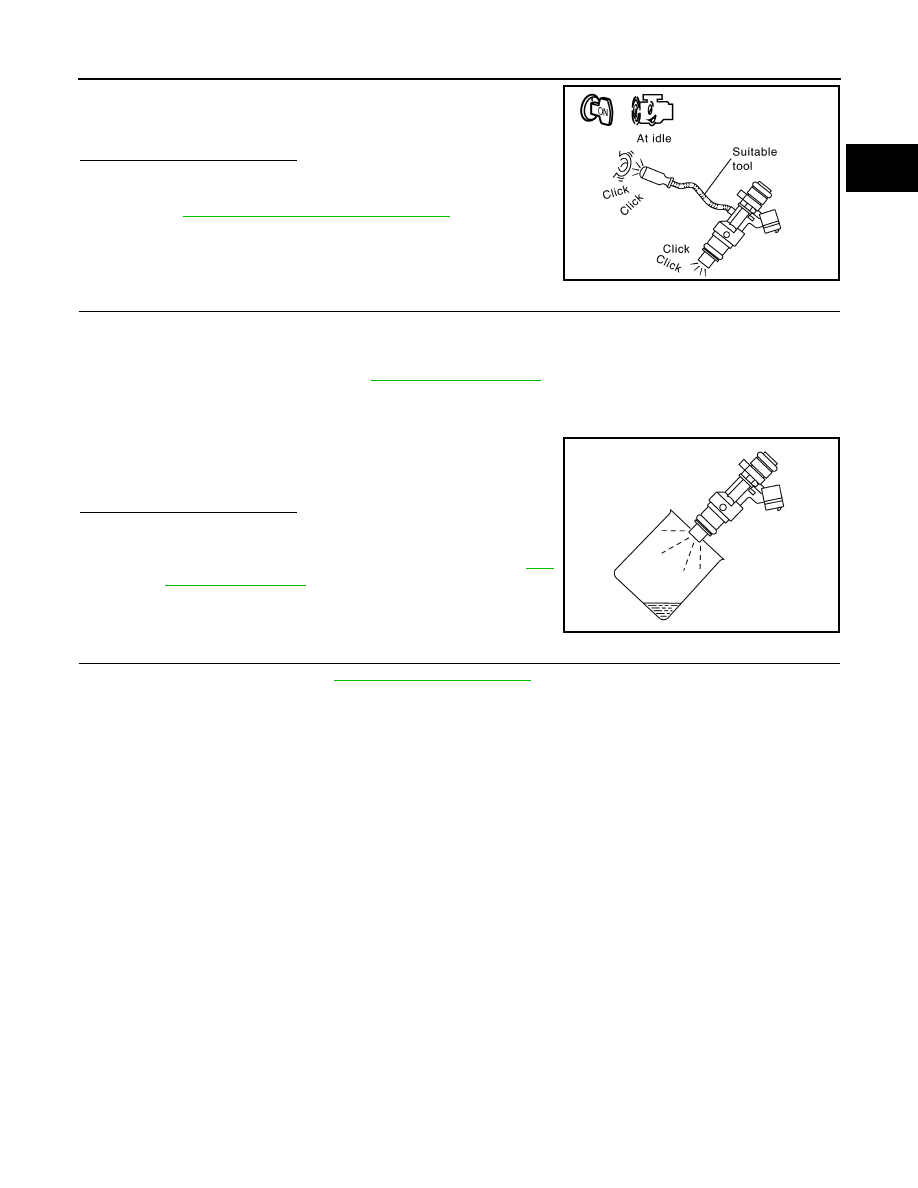
2.
Listen to each fuel injector operating sound.
Is the inspection result normal?
YES
>> GO TO 8.
NO
>> Perform trouble diagnosis for FUEL INJECTOR. Refer
to
EC-285, "Component Function Check"
.
8.
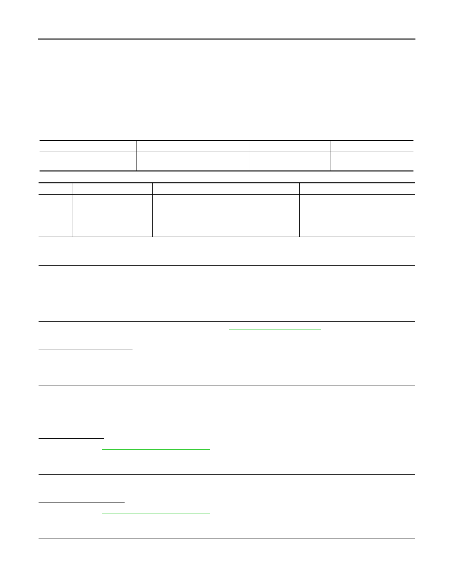
CHECK FUEL INJECTOR
1.
Turn ignition switch OFF.
2.
Confirm that the engine is cooled down and there are no fire hazards near the vehicle.
3.
Disconnect all fuel injector harness connectors.
4.
Remove fuel tube assembly. Refer to
.
Keep fuel hose and all fuel injectors connected to fuel tube.
5.
Disconnect all ignition coil harness connectors.
6.
Prepare pans or saucers under each fuel injector.
7.
Crank engine for about 3 seconds.
Is the inspection result normal?
YES
>> GO TO 9.
NO
>> Replace fuel injectors from which fuel does not spray
out. Always replace O-ring with new ones. Refer to
.
9.
CHECK INTERMITTENT INCIDENT
Check intermittent incident. Refer to
GI-33, "Intermittent Incident"
.
>> Repair or replace malfunctioning part.
Clicking noise should be heard.
PBIB3332E
Fuel should be sprayed evenly for each fuel injector.
PBIA9666J
EC-182
< DTC/CIRCUIT DIAGNOSIS >
[HR12DE (TYPE 1)]
P0172 FUEL INJECTION SYSTEM FUNCTION
P0172 FUEL INJECTION SYSTEM FUNCTION
DTC Logic
INFOID:0000000005989281
DTC DETECTION LOGIC
With the Air/Fuel Mixture Ratio Self-Learning Control, the actual mixture ratio can be brought closely to the
theoretical mixture ratio based on the mixture ratio feedback signal from the A/F sensor 1. The ECM calcu-
lates the necessary compensation to correct the offset between the actual and the theoretical ratios.
In case the amount of the compensation value is extremely large (The actual mixture ratio is too rich.), the
ECM judges the condition as the fuel injection system malfunction and lights up the MIL (2 trip detection logic).
DTC CONFIRMATION PROCEDURE
1.
PRECONDITIONING
If DTC Confirmation Procedure has been previously conducted, always turn ignition switch OFF and wait at
least 10 seconds before conducting the next test.
>> GO TO 2.
2.
PERFORM DTC CONFIRMATION PROCEDURE-I
1.
Clear the mixture ratio self-learning value. Refer to
.
2.
Start engine.
Is it difficult to start engine?
YES
>> GO TO 3.
NO
>> GO TO 4.
3.
RESTART ENGINE
If it is difficult to start engine, the fuel injection system has a malfunction, too.
Crank engine while depressing accelerator pedal.
NOTE:
When depressing accelerator pedal three-fourths (3/4) or more, the control system may not start the engine.
Do not depress accelerator pedal too much.
Does engine start?
YES
>> Go to
NO
>> Remove spark plugs and check for fouling, etc.
4.
PERFORM DTC CONFIRMATION PROCEDURE-II
1.
Start engine and let it idle for at least 10 minutes.
2.
Check 1st trip DTC.
Is 1st trip DTC detected?
YES
>> Go to
NO
>> GO TO 5.
5.
PERFORM DTC CONFIRMATION PROCEDURE-III
1.
Turn ignition switch OFF and wait at least 10 seconds.
2.
Start engine and drive the vehicle under the similar conditions to (1st trip) Freeze Frame Data for 10 min-
utes. Refer to the table below.
Sensor
Input signal to ECM
ECM function
Actuator
A/F sensor 1
Density of oxygen in exhaust gas
(Mixture ratio feedback signal)
Fuel injection control
Fuel injector
DTC No.
Trouble diagnosis name
DTC detecting condition
Possible cause
P0172
Fuel injection system too
rich
• Fuel injection system does not operate properly.
• The amount of mixture ratio compensation is too
large. (The mixture ratio is too rich.)
• A/F sensor 1
• Fuel injector
• Exhaust gas leaks
• Incorrect fuel pressure
• Mass air flow sensor
P0172 FUEL INJECTION SYSTEM FUNCTION
EC-183
< DTC/CIRCUIT DIAGNOSIS >
[HR12DE (TYPE 1)]
C
D
E
F
G
H
I
J
K
L
M
A
EC
N
P
O
Hold the accelerator pedal as steady as possible.
The similar conditions to (1st trip) Freeze Frame Data means the vehicle operation that the following con-
ditions should be satisfied at the same time.
CAUTION:
Always drive at a safe speed.
3.
Check 1st trip DTC.
Is 1st trip DTC detected?
YES
>> Go to
NO
>> INSPECTION END
Diagnosis Procedure
INFOID:0000000005989282
1.
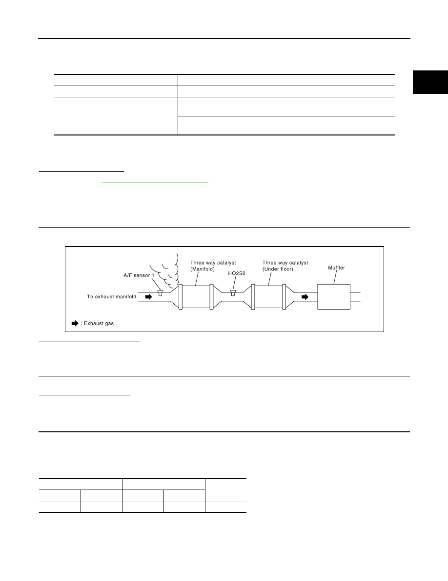
CHECK EXHAUST GAS LEAK
1.
Start engine and run it at idle.
2.
Listen for an exhaust gas leak before three way catalyst (manifold).
Is exhaust gas leak detected?
YES
>> Repair or replace.
NO
>> GO TO 2.
2.
CHECK FOR INTAKE AIR LEAK
Listen for an intake air leak after the mass air flow sensor.
Is intake air leak detected?
YES
>> Repair or replace.
NO
>> GO TO 3.
3.
CHECK A/F SENSOR 1 INPUT SIGNAL CIRCUIT FOR OPEN AND SHORT
1.
Turn ignition switch OFF.
2.
Disconnect corresponding A/F sensor 1 harness connector.
3.
Disconnect ECM harness connector.
4.
Check the continuity between A/F sensor 1 harness connector and ECM harness connector.
5.
Check the continuity between A/F sensor 1 harness connector or ECM harness connector and ground.
Engine speed
Engine speed in the freeze frame data
±
400 rpm
Vehicle speed
Vehicle speed in the freeze frame data
±
10 km/h (6 MPH)
Engine coolant temperature (T) condition
When the freeze frame data shows lower than 70
°
C (158
°
F),
T should be lower than 70
°
C (158
°
F).
When the freeze frame data shows higher than or equal to 70
°
C (158
°
F),
T should be higher than or equal to 70
°
C (158
°
F).
PBIB1216E
A/F sensor 1
ECM
Continuity
Connector
Terminal
Connector
Terminal
F50
1
F16
49
Existed
EC-184
< DTC/CIRCUIT DIAGNOSIS >
[HR12DE (TYPE 1)]
P0172 FUEL INJECTION SYSTEM FUNCTION
6.
Also check harness for short to power.
Is the inspection result normal?
YES
>> GO TO 4.
NO
>> Repair open circuit or short to ground or short to power in harness or connectors.
4.
CHECK FUEL PRESSURE
1.
Release fuel pressure to zero. Refer to
.
2.
Install fuel pressure gauge and check fuel pressure. Refer to
.
Is the inspection result normal?
YES
>> GO TO 6.
NO
>> GO TO 5.
5.
CHECK FUEL HOSES AND FUEL TUBES
Check fuel hoses and fuel tubes for clogging.
Is the inspection result normal?
YES
>> Replace fuel level sensor unit, fuel filter and fuel pump assembly. Refer to
.
NO
>> Repair or replace
6.
CHECK MASS AIR FLOW SENSOR
With CONSULT-III
1.
Install all removed parts.
2.
Check “MASS AIRFLOW” in “DATA MONITOR” mode with CONSULT-III.
With GST
1.
Install all removed parts.
2.
Check mass air flow sensor signal in “Service $01” with GST.
Is the measurement value within the specification?
YES
>> GO TO 7.
NO
>> Check connectors for rusted terminals or loose connections in the mass air flow sensor circuit or
grounds. Refer to
.
7.
CHECK FUNCTION OF FUEL INJECTOR
With CONSULT-III
1.
Start engine.
2.
Perform “POWER BALANCE” in “ACTIVE TEST” mode with CONSULT-III.
3.
Make sure that each circuit produces a momentary engine speed drop.
Without CONSULT-III
1.
Let engine idle.
A/F sensor 1
ECM
Ground
Continuity
Connector
Terminal
Connector
Terminal
F50
1
F16
49
Ground
Not existed
At idling: Approximately 350 kPa (3.5 bar, 3.57 kg/cm
2
, 51 psi)
1.0 - 4.0 g·m/sec:
at idling
2.0 - 10.0 g·m/sec:
at 2,500 rpm
1.0 - 4.0 g·m/sec:
at idling
2.0 - 10.0 g·m/sec:
at 2,500 rpm
Нет комментариевНе стесняйтесь поделиться с нами вашим ценным мнением.
Текст