Nissan March K13. Manual — part 48
CHG-6
< SYSTEM DESCRIPTION >
COMPONENT PARTS
SYSTEM DESCRIPTION
COMPONENT PARTS
CHARGING SYSTEM
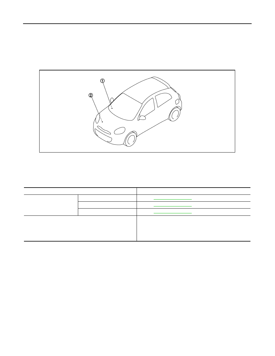
CHARGING SYSTEM : Component Parts Location
INFOID:0000000006057230
CHARGING SYSTEM : Component Description
INFOID:0000000006057231
POWER GENERATION VOLTAGE VARIABLE CONTROL SYSTEM
POWER GENERATION VOLTAGE VARIABLE CONTROL SYSTEM : Component
1.
Charge warning lamp (On the combi-
nation meter)
2.
Alternator
JMMIA0386ZZ
Component part
Description
Alternator
“B” terminal
“S” terminal
“L” terminal
Refer to
Combination meter (Charge warning lamp)
The IC voltage regulator warning function activates to illuminate
the charge warning lamp, if any of the following symptoms occur
while alternator is operating:
• Excessive voltage is produced.
• No voltage is produced.
CHG
COMPONENT PARTS
CHG-7
< SYSTEM DESCRIPTION >
C
D
E
F
G
H
I
J
K
L
B
A
O
P
N
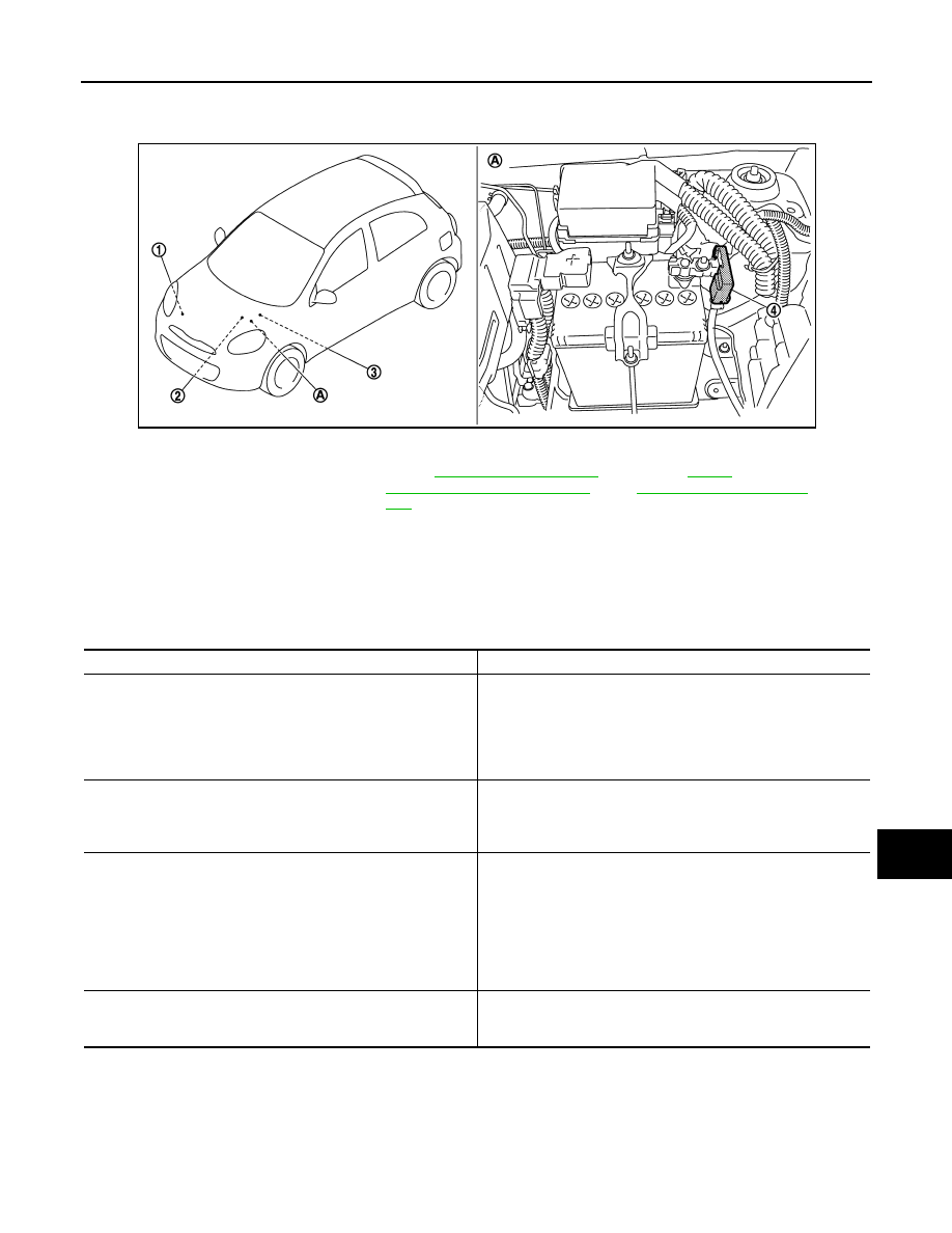
Parts Location
INFOID:0000000006067201
POWER GENERATION VOLTAGE VARIABLE CONTROL SYSTEM : Component De-
scription
INFOID:0000000006067202
1.
Alternator
2.
IPDM E/R
Refer to
SYSTEM : Component Parts Loca-
tion"
.
3.
ECM
Refer to
.
4.
Battery current sensor
A.
Battely
JMMIA0387ZZ
Component part
Description
Alternator (IC voltage regulator)
IC voltage regulator controls the power generation voltage by the
target power generation voltage based on the received power gen-
eration command signal.
When there is no power generation command signal, the alterna-
tor performs the normal power generation according to the char-
acteristic of the IC voltage regulator.
Battery current sensor
Battery current sensor is installed to the battery cable at the neg-
ative terminal, and it detects the charging/discharging current of
the battery and sends the voltage signal to ECM according to the
current value.
ECM
Battery current sensor detects the charging/discharging current of
the battery. ECM judges the battery condition based on this signal.
ECM judges whether to perform the power generation voltage
variable control according to the battery condition.
When performing the power generation voltage variable control,
ECM calculates the target power generation voltage according to
the battery condition and sends the calculated value as the power
generation command value to IPDM E/R.
IPDM E/R
IPDM E/R converts the received power generation command val-
ue into the power generation command signal (PWM signal) and
sends it to the IC voltage regulator.
CHG-8
< SYSTEM DESCRIPTION >
SYSTEM
SYSTEM
CHARGING SYSTEM
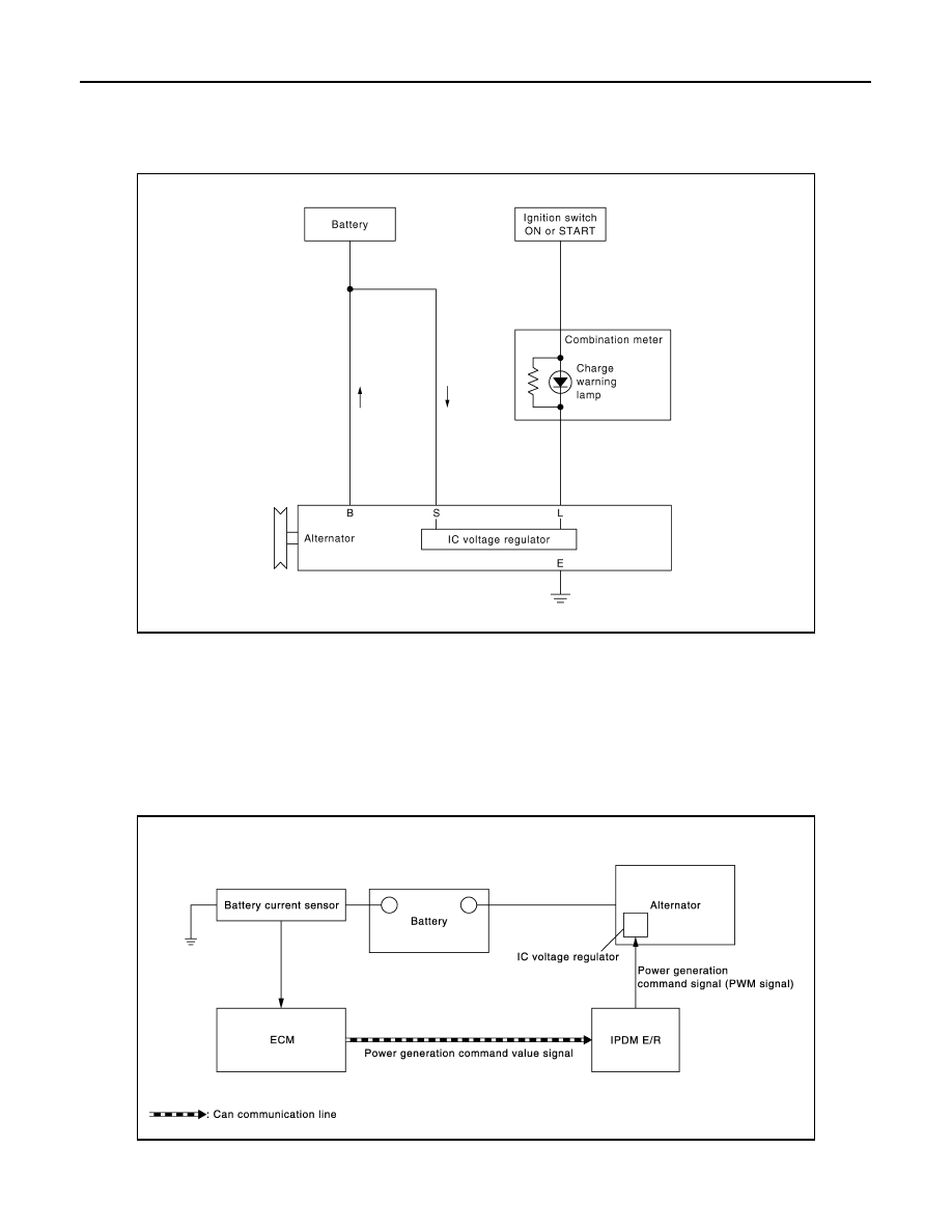
CHARGING SYSTEM : System Diagram
INFOID:0000000006057228
CHARGING SYSTEM : System Description
INFOID:0000000006057229
The alternator provides DC voltage to operate the vehicle's electrical system and to keep the battery charged.
The voltage output is controlled by the IC voltage regulator.
POWER GENERATION VOLTAGE VARIABLE CONTROL SYSTEM
POWER GENERATION VOLTAGE VARIABLE CONTROL SYSTEM : System Dia-
gram
INFOID:0000000006067199
POWER GENERATION VOLTAGE VARIABLE CONTROL SYSTEM : System De-
JPMIA0426GB
JMMIA0388GB
CHG
SYSTEM
CHG-9
< SYSTEM DESCRIPTION >
C
D
E
F
G
H
I
J
K
L
B
A
O
P
N
scription
INFOID:0000000006067200
By performing the power generation voltage variable control, the engine load due to the power generation of
the alternator is reduced and fuel consumption is decreased.
NOTE:
When any malfunction is detected in the power generation voltage variable control system, the power genera-
tion is performed according to the characteristic of the IC voltage regulator of the alternator.
Нет комментариевНе стесняйтесь поделиться с нами вашим ценным мнением.
Текст