Nissan March K13. Manual — part 426
IP-14
< REMOVAL AND INSTALLATION >
INSTRUMENT PANEL ASSEMBLY
[ ]: Number indicates step in removal procedures.
WARNING:
Before servicing, turn ignition switch OFF, disconnect battery negative terminal and wait 3 minutes or
more.
CAUTION:
When removing, always use a remover tool that is made of plastic.
REMOVAL
1.
Remove center console assembly.
1.
Shift selector lever knob in “N” position. (A/T models)
2.
Remove shift knob. (M/T models)
3.
Release the parking brake lever by turning the adjusting nut with a deep socket wrench and loosening
the cable. Refer to
PB-2, "Inspection and Adjustment"
.
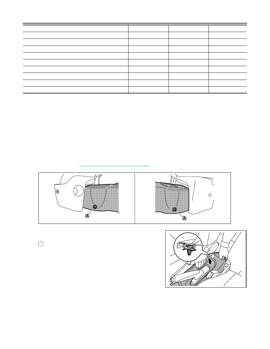
4.
Remove center console assembly fixing clips (A).
5.
Pull up center console assembly to disengage the clips.
6.
Disconnect harness connectors. (with Switches)
7.
Slide front seat RH to the rearmost position and operate to the fully reclining status.
8.
Slide front seat LH to the frontmost position and tilt seatback to the fully forward status.
Optical sensor (with Auto light)
[22]
Sunload sensor (with Auto A/C)
[23]
Glove box lid or Glove box escutcheon
[24]
Glove upper box assembly or Instrument finisher B
[25]
Glove box cover
[26]
Instrument finisher D or Passenger air bag module
[27]
Front body side welt LH
[28]
Front pillar garnish LH
[29]
Instrument side finisher LH
[30]
Instrument panel assembly
[31]
JMJIA3981ZZ
: Clip
JMJIA3982ZZ
INSTRUMENT PANEL ASSEMBLY
IP-15
< REMOVAL AND INSTALLATION >
C
D
E
F
G
H
I
K
L
M
A
B
IP
N
O
P
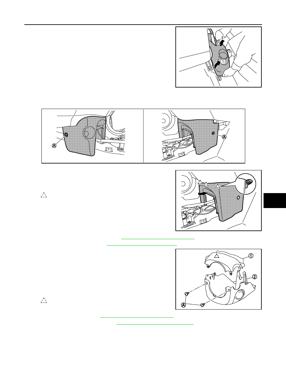
9.
Lift up rear portion of center console assembly while rotating
and remove center console assembly.
2.
Remove instrument lower center panel.
1.
Put front seat to rearmost position.
2.
Remove instrument lower center panel fixing clips (A).
3.
Pull back instrument lower center panel, and then disen-
gage the pawls.
4.
Disconnect harness connectors. (with Power socket)
3.
Remove driver air bag module. Refer to
SR-13, "Removal and Installation"
.
4.
Remove steering wheel. Refer to
ST-9, "Removal and Installation"
5.
Remove steering column covers.
1.
Remove steering column cover fixing screws (A).
2.
Place the tilt to the lowest level.
3.
Pull up steering column upper cover (1), and then disen-
gage steering column upper cove fixing pawls.
4.
Remove steering column upper cover.
5.
Pull down the steering column lower cover (2), and then
remove the steering column lower cover.
6.
Remove spiral cable. Refer to
SR-16, "Removal and Installation"
.
7.
Remove combination switch. Refer to
BCS-58, "Removal and Installation"
JMJIA4077ZZ
JMJIA3983ZZ
: Pawl
JMJIA3984ZZ
: Pawl
JMJIA3985ZZ
IP-16
< REMOVAL AND INSTALLATION >
INSTRUMENT PANEL ASSEMBLY
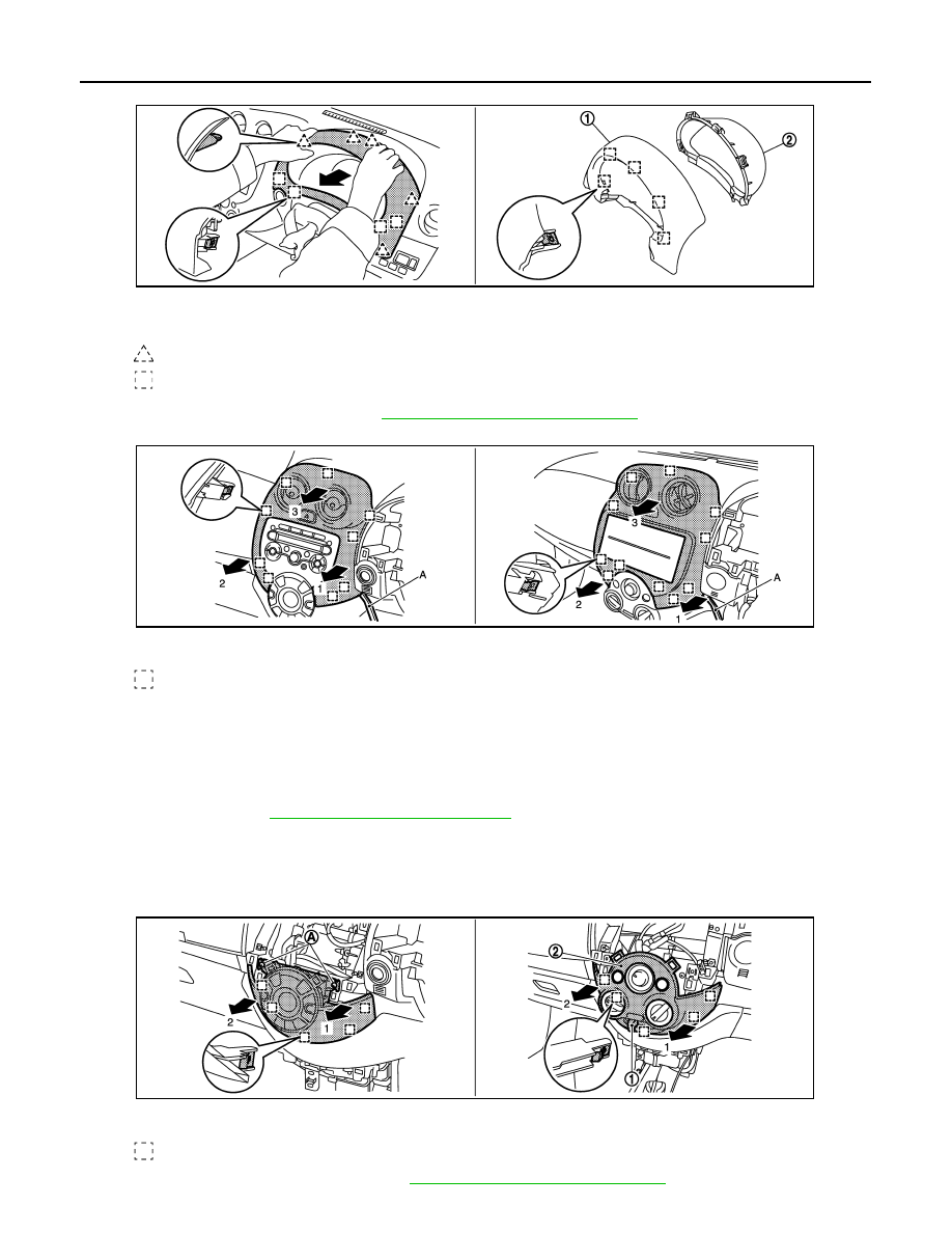
8.
Remove instrument finisher A.
Pull instrument finisher A (1) and cluster lid A (2) as a set toward the vehicle rear and disengage pawls
and metal clips.
9.
Remove combination meter. Refer to
MWI-51, "Removal and Installation"
10. Remove cluster lid C.
1.
Insert a remover tool (A) between cluster lid C and instrument panel assembly, and then disengage
metal clips of lower side.
2.
Pull back cluster lid C, and then disengage metal clips of upper side.
3.
Disconnect harness connectors.
11. Remove audio unit or instrument pocket.
• Audio unit: Refer to
AV-16, "Removal and Installation"
• Instrument pocket
- Remove instrument pocket fixing screws.
- Pull back instrument pocket.
- Remove harness connector and antenna.
12. Remove A/C controller (with Auto A/C) or A/C finisher (with Manual A/C).
• A/C controller (with Auto A/C): Refer to
HAC-75, "Removal and Installation"
.
: Pawl
: Metal clip
JMJIA3986ZZ
Cluster lid C (with Auto A/C)
Cluster lid C (with Manual A/C)
: Metal clip
JMJIA3987ZZ
A/C controller (with Auto A/C)
A/C finisher (with Manual A/C)
: Metal clip
JMJIA3988ZZ
INSTRUMENT PANEL ASSEMBLY
IP-17
< REMOVAL AND INSTALLATION >
C
D
E
F
G
H
I
K
L
M
A
B
IP
N
O
P
- Remove screws (A).
- Pull back A/C controller, and then disengage metal clips.
- Disconnect harness connector.
• A/C finisher (with Manual A/C)
- Remove intake door lever knob (1). Refer to
HAC-115, "Removal and Installation"
.
- Pull back A/C finisher (2), and then disengage metal clips.
13. Remove A/C control fixing screws (with Manual A/C). Refer to
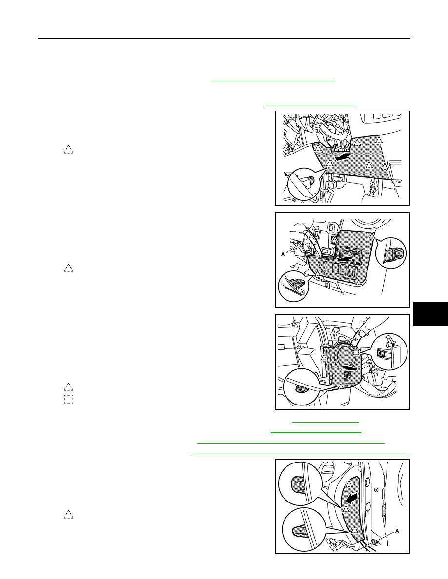
14. Remove instrument lower panel RH.
Pull back the instrument lower panel RH, and then disengage
the pawls.
15. Remove switch panel.
1.
Insert a remover tool (A) between switch panel and instru-
ment panel assembly, and then disengage pawls.
2.
Pull back switch panel.
3.
Disconnect harness connectors.
16. Remove instrument finisher E.
1.
Insert a remover tool (A) between instrument finisher E and
instrument panel assembly, and then disengage pawls and
metal clip.
2.
Pull back instrument finisher E.
3.
Disconnect harness connectors. (with Intelligent key or Auto
A/C)
17. Remove data link connector from instrument panel assembly. Refer to
.
18. Remove hood and fuel lid opener lever mounting bolts. Refer to
.
19. Remove front body side welt RH. Refer to
INT-23, "BODY SIDE WELT : Removal and Installation"
.
20. Remove front pillar garnish RH. Refer to
INT-22, "FRONT PILLAR GARNISH : Removal and Installation"
21. Remove instrument side finisher RH.
1.
Insert a remover tool (A) between instrument side finisher
RH and instrument lower panel RH, and then disengage
pawls.
2.
Pull the instrument side finisher RH crosswise.
: Pawl
JMJIA3989ZZ
: Pawl
JMJIA3990ZZ
: Pawl
: Metal clip
JMJIA3991ZZ
: Pawl
JMJIA3997ZZ
Нет комментариевНе стесняйтесь поделиться с нами вашим ценным мнением.
Текст