Nissan March K13. Manual — part 499
PCS-78
< DTC/CIRCUIT DIAGNOSIS >
[POWER DISTRIBUTION SYSTEM]
B2616 IGNITION RELAY CIRCUIT
YES
>> Replace BCM. Refer to
BCS-57, "Removal and Installation"
NO
>> Repair or replace harness.
3.
CHECK IGNITION RELAY GROUND CIRCUIT
1.
Turn ignition switch OFF.
2.
Check continuity between ignition relay harness connector and ground.
Is the inspection result normal?
YES
>> GO TO 4.
NO
>> Repair ignition relay ground circuit.
4.
CHECK IGNITION RELAY POWER SUPPLY CIRCUIT-2
1.
Turn ignition switch ON.
2.
Check voltage between ignition relay harness connector and ground.
Is the inspection result normal?
YES
>> GO TO 5.
NO
>> Check continuity open or short between ignition relay and battery.
5.
CHECK IGNITION RELAY
PCS-78, "Component Inspection"
.
Is the inspection result normal?
YES
>> GO TO 6.
NO
>> Replace ignition relay.
6.
CHECK INTERMITTENT INCIDENT
GI-33, "Intermittent Incident"
>> INSPECTION END
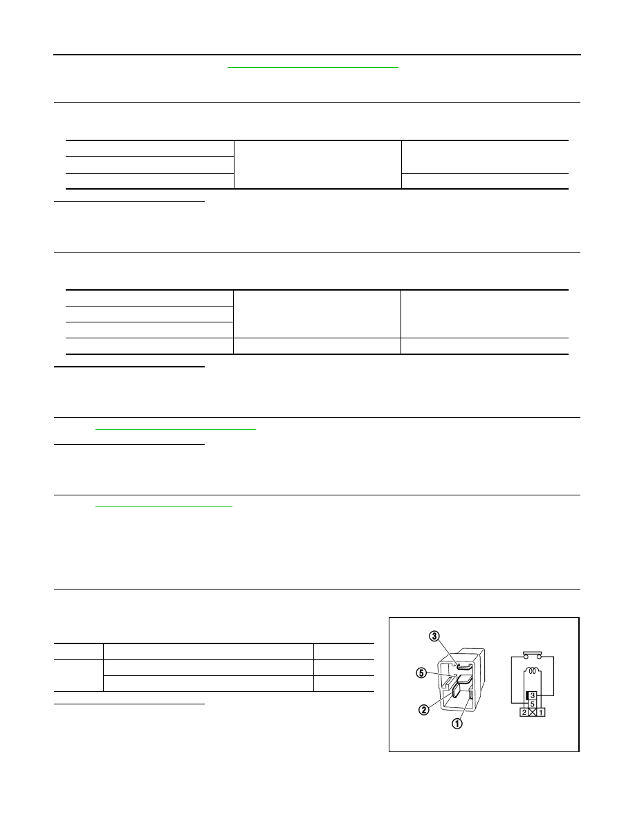
Component Inspection
INFOID:0000000005998925
1.
CHECK IGNITION RELAY
1.
Turn ignition switch OFF.
2.
Remove ignition relay.
3.
Check the continuity between ignition relay terminals.
Is the inspection result normal?
YES
>> INSPECTION END
NO
>> Replace Ignition relay
Ignition relay
Ground
Continuity
Terminal
1
Existed
(+)
(–)
Voltage (V)
(Approx.)
Ignition relay
Terminal
5
Ground
Battery voltage
Terminals
Condition
Continuity
3 and 5
12 V direct current supply between terminals 1 and 2
Existed
No current supply
Not existed
PBIB0098E
PCS
B2618 BCM
PCS-79
< DTC/CIRCUIT DIAGNOSIS >
[POWER DISTRIBUTION SYSTEM]
C
D
E
F
G
H
I
J
K
L
B
A
O
P
N
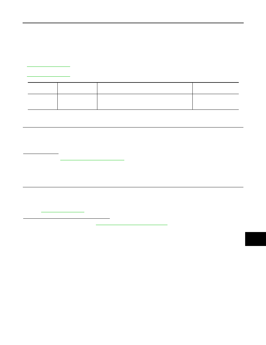
B2618 BCM
DTC Logic
INFOID:0000000005998926
DTC DETECTION LOGIC
NOTE:
• If DTC B2618 is displayed with DTC U1000, first perform the trouble diagnosis for DTC U1000. Refer to
• If DTC B2618 is displayed with DTC U1010, first perform the trouble diagnosis for DTC U1010. Refer to
DTC CONFIRMATION PROCEDURE
1.
PERFORM DTC CONFIRMATION PROCEDURE
1.
Turn ignition switch ON under the following conditions, and wait for 1 second or more.
-
Selector lever is in the P or N position
-
Do not depress brake pedal
2.
Check “Self-diagnosis result” with CONSULT-III.
Is DTC detected?
YES
>> Go to
NO
>> INSPECTION END
Diagnosis Procedure
INFOID:0000000005998927
1.
INSPECTION START
1.
Turn ignition switch ON.
2.
Select “Self-diagnosis result” mode with CONSULT-III.
3.
Touch “ERASE”.
4.
Perform DTC Confirmation Procedure.
See
.
Is the 1st trip DTC B2618 displayed again?
YES
>> Replace BCM. Refer to
BCS-57, "Removal and Installation"
NO
>> INSPECTION END
DTC No.
Trouble diagnosis
name
DTC detecting condition
Possible cause
B2618
BCM
An immediate operation of ignition relay (IPDM E/R) is re-
quested by BCM, but there is no response for more than
1 second
BCM
PCS-80
< DTC/CIRCUIT DIAGNOSIS >
[POWER DISTRIBUTION SYSTEM]
B261A PUSH-BUTTON IGNITION SWITCH
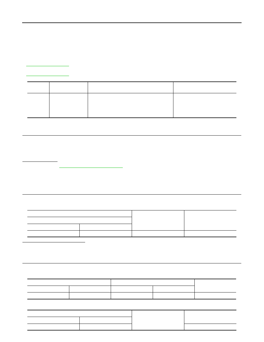
B261A PUSH-BUTTON IGNITION SWITCH
DTC Logic
INFOID:0000000005998928
DTC DETECTION LOGIC
NOTE:
• If DTC B261A is displayed with DTC U1000, first perform the trouble diagnosis for DTC U1000. Refer to
.
• If DTC B261A is displayed with DTC U1010, first perform the trouble diagnosis for DTC U1010. Refer to
.
DTC CONFIRMATION PROCEDURE
1.
PERFORM DTC CONFIRMATION PROCEDURE
1.
Press the push-button ignition switch under the following conditions, and wait for 1 second or more.
-
Selector lever is in the P or N position
-
Do not depress brake pedal
2.
Check “Self-diagnosis result” with CONSULT-III.
Is DTC detected?
YES
>> Go to
NO
>> INSPECTION END
Diagnosis Procedure
INFOID:0000000005998929
1.
CHECK IGNITION SWITCH OUTPUT SIGNAL (PUSH-BUTTON IGNITION SWITCH)
1.
Disconnect push-button ignition switch connector and IPDM E/R connector.
2.
Check voltage between push-button ignition switch harness connector and ground.
Is the inspection result normal?
YES
>> GO TO 3.
NO
>> GO TO 2.
2.
CHECK PUSH-BUTTON IGNITION SWITCH CIRCUIT (BCM)
1.
Disconnect BCM connector.
2.
Check continuity between BCM harness connector and push-button ignition switch harness connector.
3.
Check continuity between push-button ignition switch harness connector and ground.
DTC No.
Trouble diagnosis
name
DTC detecting condition
Possible cause
B261A
PUSH-BTN IGN SW
BCM detects a difference of signal for 1 second or
more between the following items.
• Push-button ignition switch signal
• Push-button ignition switch status siganl (CAN)
• Harness or connectors
(Push-button ignition switch circuit
is open or shorted.)
• BCM
• IPDM E/R
(+)
(–)
Voltage (V)
(Approx.)
Push-button ignition switch
Connector
Terminal
M101
8
Ground
12
BCM
Push-button ignition switch
Continuity
Connector
Terminal
Connector
Terminal
M71
100
M101
8
Existed
Push-button ignition switch
Ground
Continuity
Connector
Terminal
M101
8
Not existed
PCS
B261A PUSH-BUTTON IGNITION SWITCH
PCS-81
< DTC/CIRCUIT DIAGNOSIS >
[POWER DISTRIBUTION SYSTEM]
C
D
E
F
G
H
I
J
K
L
B
A
O
P
N
Is the inspection result normal?
YES
>> Replace BCM. Refer to
BCS-57, "Removal and Installation"
NO
>> Repair or replace harness.
3.
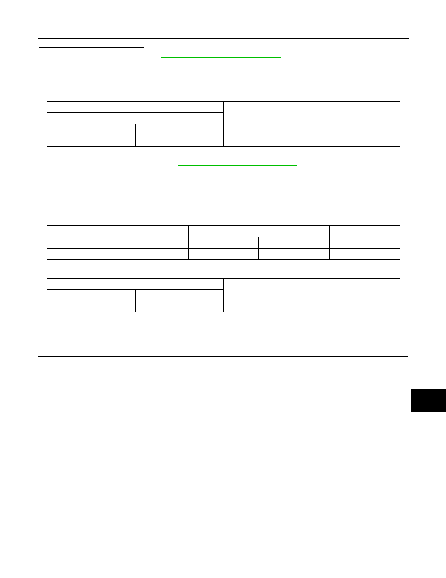
CHECK IGNITION SWITCH OUTPUT SIGNAL (IPDM E/R)
Check voltage between IPDM E/R harness connector and ground.
Is the inspection result normal?
YES
>> Replace IPDM E/R. Refer to
PCS-28, "Removal and Installation"
.
NO
>> GO TO 4.
4.
CHECK PUSH-BUTTON IGNITION SWITCH CIRCUIT (IPDM E/R)
1.
Disconnect IPDM E/R connector.
2.
Check continuity between IPDM E/R harness connector and push-button ignition switch harness connec-
tor.
3.
Check continuity between push-button ignition switch harness connector and ground.
Is the inspection result normal?
YES
>> GO TO 5.
NO
>> Repair or replace harness.
5.
CHECK INTERMITTENT INCIDENT
GI-33, "Intermittent Incident"
.
>> INSPECTION END
(+)
(–)
Voltage (V)
(Approx.)
IPDM E/R
Connector
Terminal
E17
81
Ground
12
IPDM E/R
Push-button ignition switch
Continuity
Connector
Terminal
Connector
Terminal
E17
81
M101
8
Existed
Push-button ignition switch
Ground
Continuity
Connector
Terminal
M101
8
Not existed
Нет комментариевНе стесняйтесь поделиться с нами вашим ценным мнением.
Текст