Nissan March K13. Manual — part 587

B2612 STEERING STATUS
SEC-87
< DTC/CIRCUIT DIAGNOSIS >
[WITH INTELLIGENT KEY SYSTEM]
C
D
E
F
G
H
I
J
L
M
A
B
SEC
N
O
P
B2612 STEERING STATUS
DTC Logic
INFOID:0000000006038562
DTC DETECTION LOGIC
NOTE:
• If DTC B2612 is displayed with DTC U1000, first perform the trouble diagnosis for DTC U1000. Refer to
• If DTC B2612 is displayed with DTC U1010, first perform the trouble diagnosis for DTC U1010. Refer to
DTC CONFIRMATION PROCEDURE
1.
PERFORM DTC CONFIRMATION PROCEDURE 1
1.
Press push-button ignition switch under the following conditions and wait 1 second or more.
-
Selector lever: In the P position
-
Brake pedal: Not depressed
2.
Check DTC in “Self Diagnostic Result” mode of “BCM” using CONSULT-III.
Is DTC detected?
YES
>> Go to
NO
>> GO TO 2.
2.
PERFORM DTC CONFIRMATION PROCEDURE 2
1.
Turn ignition switch ON.
2.
Turn ignition switch OFF.
3.
Press driver side door switch and wait 1 second or more.
4.
Check DTC in “Self Diagnostic Result” mode of “BCM” using CONSULT-III.
Is DTC detected?
YES
>> Go to
NO
>> INSPECTION END
Diagnosis Procedure
INFOID:0000000006038563
1.
CHECK IPDM E/R INPUT SIGNAL
1.
Turn ignition switch OFF.
2.
Check voltage between IPDM E/R harness connector and ground.
NOTE:
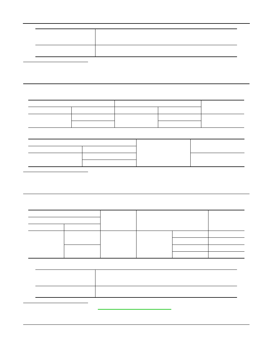
DTC No.
Trouble diagnosis name
DTC detecting condition
Possible causes
B2612
S/L STATUS
The following 2 state signals are different.
• Steering lock state recognition of BCM
• Steering lock state signal from IPDM E/R
• Harness or connectors
(The CAN communication line is open or
shorted.)
• Harness or connectors
(Steering lock unit circuit is open or shorted.)
• Steering lock unit
• IPDM E/R
• BCM
(+)
(–)
Condition
Voltage (V)
(Approx.)
IPDM E/R
Connector
Terminal
E17
88
Ground
Steering lock unit
Unlock
12
Lock
0
89
Unlock
0
Lock
12
SEC-88
< DTC/CIRCUIT DIAGNOSIS >
[WITH INTELLIGENT KEY SYSTEM]
B2612 STEERING STATUS
Is the inspection result normal?
YES
>> GO TO 3.
NO
>> GO TO 2.
2.
CHECK IPDM E/R INPUT SIGNAL CIRCUIT
1.
Disconnect IPDM E/R connector and steering lock unit connector.
2.
Check continuity between IPDM E/R harness connector and steering lock unit harness connector.
3.
Check continuity between IPDM E/R harness connector and ground.
Is the inspection result normal?
YES
>> Replace steering lock unit.
NO
>> Repair or replace harness.
3.
CHECK BCM INPUT SIGNAL
1.
Turn ignition switch OFF.
2.
Check voltage between BCM harness connector and ground.
NOTE:
Is the inspection result normal?
YES
>> Replace BCM. Refer to
BCS-57, "Removal and Installation"
NO
>> GO TO 4.
4.
CHECK BCM INPUT SIGNAL CIRCUIT
1.
Disconnect BCM connector and steering lock unit connector.
2.
Check continuity between BCM harness connector and steering lock unit harness connector.
To lock the steering
1.
Set the selector lever in the P position.
2.
Turn the power supply position to the OFF position.
3.
Press any door switch.
To unlock the steering
1.
Set the selector lever in the P position.
2.
Press the push-button ignition switch with brake pedal not depressed.
IPDM E/R
Steering lock unit
Continuity
Connector
Terminal
Connector
Terminal
E17
88
M12
3
Existed
89
8
IPDM E/R
Ground
Continuity
Connector
Terminal
E17
88
Not existed
89
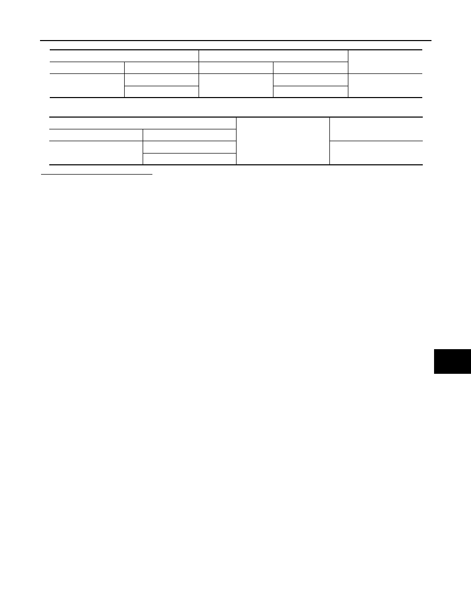
(+)
(–)
Condition
Voltage (V)
(Approx.)
BCM
Connector
Terminal
M71
107
Ground
Steering lock unit
Lock
0
Unlock
12
108
Lock
12
Unlock
0
To lock the steering
1.
Set the selector lever in the P position.
2.
Turn the power supply position to the OFF position.
3.
Press any door switch.
To unlock the steering
1.
Set the selector lever in the P position.
2.
Press the push-button ignition switch with brake pedal not depressed.
B2612 STEERING STATUS
SEC-89
< DTC/CIRCUIT DIAGNOSIS >
[WITH INTELLIGENT KEY SYSTEM]
C
D
E
F
G
H
I
J
L
M
A
B
SEC
N
O
P
3.
Check continuity between BCM harness connector and ground.
Is the inspection result normal?
YES
>> Replace steering lock unit.
NO
>> Repair or replace harness.
BCM
Steering lock unit
Continuity
Connector
Terminal
Connector
Terminal
M71
107
M12
3
Existed
108
8
BCM
Ground
Continuity
Connector
Terminal
M71
107
Not existed
108

SEC-90
< DTC/CIRCUIT DIAGNOSIS >
[WITH INTELLIGENT KEY SYSTEM]
B2619 BCM
B2619 BCM
DTC Logic
INFOID:0000000006038564
DTC DETECTION LOGIC
DTC CONFIRMATION PROCEDURE
1.
PERFORM DTC CONFIRMATION PROCEDURE
1.
Press push-button ignition switch under the following conditions and wait 1 second or more.
-
Selector lever: In the P position
-
Brake pedal: Not depressed
2.
Check DTC in “Self Diagnostic Result” of “BCM” using CONSULT-III.
Is DTC detected?
YES
>> Go to
NO
>> INSPECTION END
Diagnosis Procedure
INFOID:0000000006038565
1.
INSPECTION START
1.
Turn ignition switch ON.
2.
Select “Self Diagnostic Result” mode of “BCM” using CONSULT-III.
3.
Touch “ERASE”.
4.
Perform DTC CONFIRMATION PROCEDURE for DTC B2619. Refer to
Is DTC detected?
YES
>> Replace BCM. Refer to
BCS-57, "Removal and Installation"
NO
>> INSPECTION END
DTC No.
Trouble diagnosis name
DTC detecting condition
Possible cause
B2619
BCM
There is a difference between power supply output to
steering lock unit and steering lock unit F/B result.
BCM
Нет комментариевНе стесняйтесь поделиться с нами вашим ценным мнением.
Текст