Nissan March K13. Manual — part 235

P0107, P0108 MAP SENSOR
EC-401
< DTC/CIRCUIT DIAGNOSIS >
[HR12DE (TYPE 2)]
C
D
E
F
G
H
I
J
K
L
M
A
EC
N
P
O
P0107, P0108 MAP SENSOR
DTC Logic
INFOID:0000000006037309
DTC DETECTION LOGIC
NOTE:
If DTC P0107 or P0108 is displayed with DTC P1229, first perform the trouble diagnosis for DTC P1229. Refer
to
DTC CONFIRMATION PROCEDURE
1.
PRECONDITIONING
If DTC Confirmation Procedure has been previously conducted, always turn ignition switch OFF and wait atle-
ast 10 seconds before conducting the next test.
>> GO TO 2.
2.
PERFORM DTC CONFIRMATION PROCEDURE
1.
Turn ignition switch ON and wait at least 5 seconds.
2.
Check 1st trip DTC.
Is DTC 1st trip detected?
YES
>> Go to
XX-XX, "*****"
.
NO
>> INSPECTION END
Diagnosis Procedure
INFOID:0000000006044842
1.
CHECK MAP SENSOR POWER SUPPLY CIRCUIT
1.
Disconnect manifold absolute pressure sensor (MAP) sensor harness connector.
2.
Turn ignition switch ON.
3.
Check the voltage between MAP sensor harness connector and ground.
Is the inspection result normal?
YES
>> GO TO 2.
NO
>> Repair open circuit, short to ground or short to power in harness or connectors.
2.
CHECK MAP SENSOR GROUND CIRCUIT FOR OPEN AND SHORT
1.
Turn ignition switch OFF.
2.
Disconnect ECM harness connector.
3.
Check the continuity between MAP sensor harness connector and ECM harness connector.
DTC No.
Trouble diagnosis name
DTC detecting condition
Possible cause
P0107
Manifold absolute pressure
sensor circuit low input
An excessively low voltage from the sensor
is sent to ECM.
• Harness or connectors
(The sensor circuit is open or shorted.)
• Manifold absolute pressure sensor
P0108
Manifold absolute pressure
sensor circuit high input
An excessively high voltage from the sensor
is sent to ECM.
• Harness or connectors
(The sensor circuit is open or shorted)
• Manifold absolute pressure sensor
• Intake air leaks
+
-
Voltage (V)
MAP sensor
Ground
Connector
Terminal
F50
1
Ground
Approx. 5

EC-402
< DTC/CIRCUIT DIAGNOSIS >
[HR12DE (TYPE 2)]
P0107, P0108 MAP SENSOR
4.
Also check harness for short to ground and power.
Is the inspection result normal?
YES
>> GO TO 3.
NO
>> Repair open circuit, short to ground or short to power in harness or connectors.
3.
CHECK MAP SENSOR INTPUT SIGNAL CIRCUIT FOR OPEN AND SHORT
1.
Check the continuity between MAP sensor harness connector and ECM harness connector.
2.
Also check harness for short to ground and power.
Is the inspection result normal?
YES
>> GO TO 4.
NO
>> Repair open circuit, short to ground or short to power in harness or connectors.
4.
CHECK MAP SENSOR
Check map sensor. Refer to
XX-XX, "*****"
.
Is the inspection result normal?
YES
>> GO TO 5.
NO
>> Replace MAP sensor.
5.
CHECK INTERMITTENT INCIDENT
Check intermittent incident. Refer to
XX-XX, "*****"
.
>> INSPECTION END
Component Inspection
INFOID:0000000006044845
1.
CHECK MAP SENSOR-I
1.
Turn ignition switch OFF.
2.
Start engine and warm it up to normal operating temperature.
3.
Turn ignition switch OFF, wait at least 5 seconds and then turn ON.
4.
Check the voltage between ECM harness connector terminals as follows.
NOTE:
• To avoid the influence of intake manifold vacuum, check the voltage 1 or more minutes past after engine
is stopped.
• Because the sensor is absolute pressure sensor, output value may differ depending on atmospheric
pressure and altitude.
5.
Measure the atmospheric pressure.
NOTE:
+
-
Continuity
MAP sensor
ECM
Connector
Terminal
Connector
Terminal
F50
3
F102
96
Existed
+
-
Continuity
MAP sensor
ECM
Connector
Terminal
Connector
Terminal
F50
2
F101
38
Existed
ECM
+
–
Connector
Terminal
Connector
Terminal
F101
38
F102
96
P0107, P0108 MAP SENSOR
EC-403
< DTC/CIRCUIT DIAGNOSIS >
[HR12DE (TYPE 2)]
C
D
E
F
G
H
I
J
K
L
M
A
EC
N
P
O
As the atmospheric pressure described on the synoptic chart is the value at sea level, compensate the
pressure with the following chart.
6.
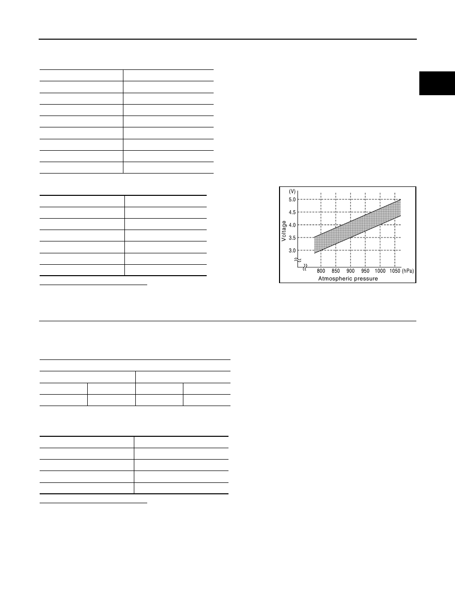
Check the manifold absolute pressure sensor value corresponding to the atmospheric pressure.
Is the inspection result normal?
YES
>> GO TO 2.
NO
>> Replace MAP sensor.
2.
CHECK MAP SENSOR-II
1.
Start engine and let it idle.
2.
Check intake manifold vacuum.
3.
Check the voltage between ECM harness connector terminals as per the following.
4.
Confirm the difference of the voltage when engine is stopped and at idling is within the values shown in
the following chart.
Is the inspection result normal?
YES
>> INSPECTION END
NO
>> Replace MAP sensor.
Altitude (m)
Compensated pressure (hPa)
0
0
200
-24
400
-47
600
-70
800
-92
1000
-114
1500
-168
2000
-218
Atmospheric pressure (hPa)
Voltage (V)
800
3.1 – 3.7
850
3.3 – 3.9
900
3.5 – 4.1
950
3.8 – 4.3
1000
4.0 – 4.6
1050
4.2 – 4.8
JMBIA0870GB
ECM
+
–
Connector
Terminal
Connector
Terminal
F101
38
F102
96
Intake manifold vacuum
Voltage difference (V)
-40kPa (-300mmHg)
1.5 – 2.0
-53.3kPa (-400mmHg)
2.0 – 2.6
-66.7kPa (-500mmHg)
2.6 – 3.2
-80kPa (-600mmHg)
3.2 – 3.8

EC-404
< DTC/CIRCUIT DIAGNOSIS >
[HR12DE (TYPE 2)]
P0117, P0118 ECT SENSOR
P0117, P0118 ECT SENSOR
DTC Logic
INFOID:0000000006037333
DTC DETECTION LOGIC
DTC CONFIRMATION PROCEDURE
1.
PRECONDITIONING
If DTC Confirmation Procedure has been previously conducted, always turn ignition switch OFF and wait at
least 10 seconds before conducting the next test.
>> GO TO 2.
2.
PERFORM DTC CONFIRMATION PROCEDURE
1.
Turn ignition switch ON and wait at least 5 seconds.
2.
Check DTC.
Is DTC detected?
YES
>> Go to
NO
>> INSPECTION END
Diagnosis Procedure
INFOID:0000000006037334
1.
CHECK ECT SENSOR POWER SUPPLY CIRCUIT
1.
Disconnect engine coolant temperature (ECT) sensor harness connector.
2.
Turn ignition switch ON.
3.
Check the voltage between ECT sensor harness connector and ground.
Is the inspection result normal?
YES
>> GO TO 2.
NO
>> Repair open circuit or short to ground or short to power in harness or connectors.
2.
CHECK ECT SENSOR GROUND CIRCUIT FOR OPEN AND SHORT
1.
Turn ignition switch OFF.
2.
Disconnect ECM harness connector.
3.
Check the continuity between ECT sensor harness connector and ECM harness connector.
4.
Also check harness for short to ground and short to power.
Is the inspection result normal?
YES
>> GO TO 3.
NO
>> Repair open circuit or short to ground or short to power in harness or connectors.
3.
CHECK ENGINE COOLANT TEMPERATURE SENSOR
DTC No.
Trouble diagnosis name
DTC detecting condition
Possible cause
P0117
Engine coolant temperature
sensor circuit low input
An excessively low voltage from the sensor
is sent to ECM.
• Harness or connectors
(The sensor circuit is open or shorted.)
• Engine coolant temperature sensor
P0118
Engine coolant temperature
sensor circuit high input
An excessively high voltage from the sensor
is sent to ECM.
ECT sensor
Ground
Voltage
Connector
Terminal
F28
1
Ground
Approx. 5 V
ECT sensor
ECM
Continuity
Connector
Terminal
Connector
Terminal
F28
2
F16
44
Existed
Нет комментариевНе стесняйтесь поделиться с нами вашим ценным мнением.
Текст