Nissan March K13. Manual — part 369
HAC-10
< SYSTEM DESCRIPTION >
[AUTOMATIC AIR CONDITIONER]
COMPONENT PARTS
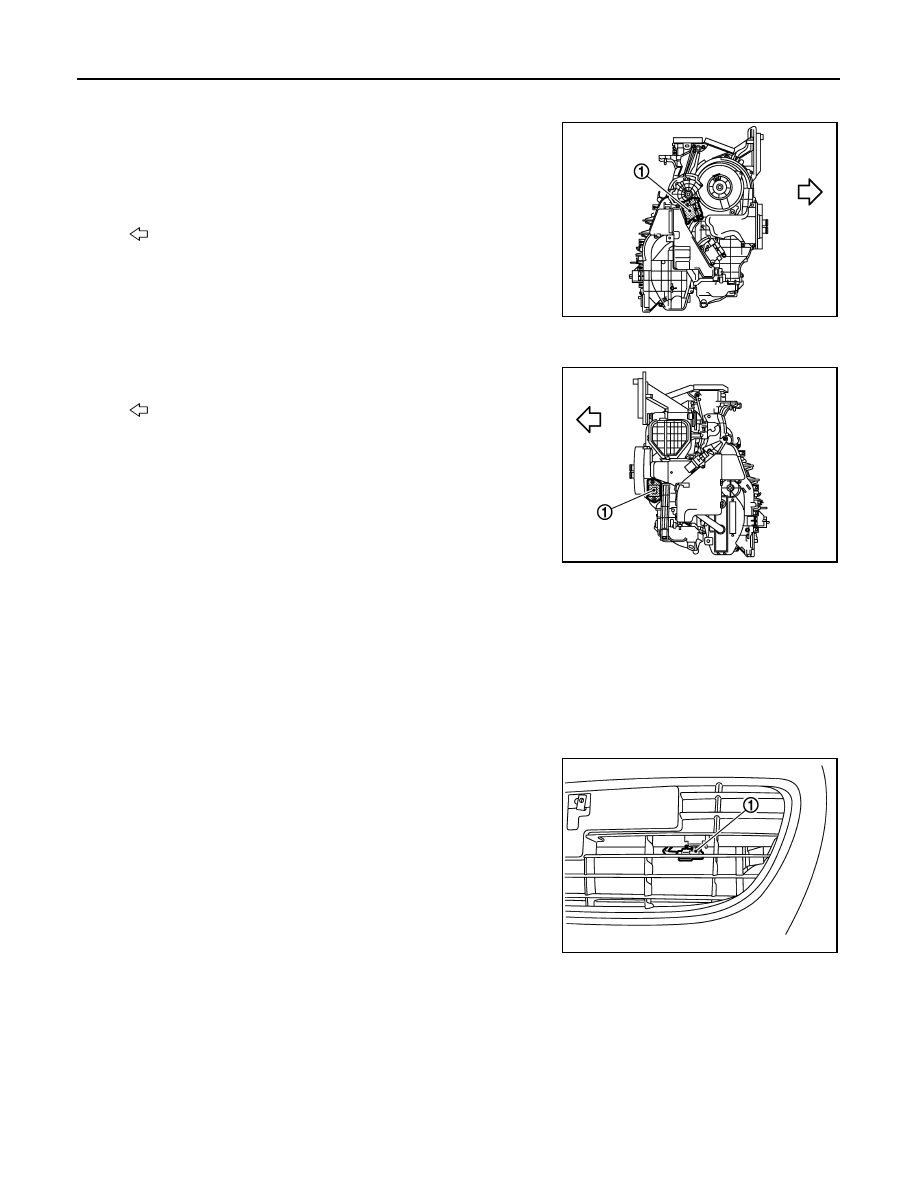
A/C UNIT ASSEMBLY : Mode Door Motor
INFOID:0000000006024038
• The mode door motor (1) is installed to the A/C unit assembly.
• Step motor system is adopted for the mode door motor.
• When a drive signal is input from auto amp. to door motor, a step
motor built into the door motor rotates according to the drive signal,
and then stops at the position of target door.
A/C UNIT ASSEMBLY : Power Transistor
INFOID:0000000006043955
• The power transistor (1) attached to A/C unit assembly.
• The power transistor controls the transmitting voltage to blower
motor base on the gate voltage from A/C auto amp.
• The power transistor is set for low voltage drop, therefore it dose
not require high relay while transmitting max voltage to blower
motor.
COMPRESSOR
COMPRESSOR : Magnet Clutch
INFOID:0000000006024048
• The magnet clutch is the device that drives the compressor with the signal from IPDM E/R.
• Compressor is driven by the magnet clutch which is charged magnetic force by electrified.
• IPDM E/R controls magnet clutch by turning the built in A/C relay to ON
⇔
OFF according to ECM request.
Ambient Sensor
INFOID:0000000006024023
COMPONENT DESCRIPTION
• The ambient sensor (1) is installed on the middle of radiator upper
support.
• The ambient sensor converts the ambient temperature detected
with thermistor into the voltage, and the A/C auto amp. inputs this
voltage.
AMBIENT TEMPERATURE CORRECTION
• The A/C auto amp. inputs the temperature detected with the ambient sensor as the ambient temperature.
• Perform the correction of the temperature detected with the ambient sensor for air conditioner control and for
ambient temperature display.
• Since the engine heat influences on the ambient sensor during idling condition, the A/C auto amp. retards
the ambient temperature indication of the combination meter to avoid the effect of steep temperature
change.
• Select and use the initial value of ambient temperature data depending on the coolant temperature when
turning the ignition switch from OFF to ON. Use the detection temperature of the ambient sensor at low cool-
: Vehicle front
JMIIA0696ZZ
: Vehicle front
JMIIA0699ZZ
JMIIA0691ZZ
COMPONENT PARTS
HAC-11
< SYSTEM DESCRIPTION >
[AUTOMATIC AIR CONDITIONER]
C
D
E
F
G
H
J
K
L
M
A
B
HAC
N
O
P
ant temperature [less than approximately 56
°
C (133
°
F)]. Use the memory data (before the ignition switch is
OFF) when the engine is warming up [approximately 56
°
C (133
°
F) or more].
• Do not perform the correction of the ambient temperature when the detection temperature of the ambient
temperature is less than approximately
−
20
°
C (–4
°
F).
SET TEMPERATURE CORRECTION
The A/C auto amp. performs the correction to the target temperature set by the temperature control switch so
as to match the temperature felt by the passengers depending on the ambient temperature detected with the
ambient sensor and controls it so that the interior air temperature is always the most suitable.
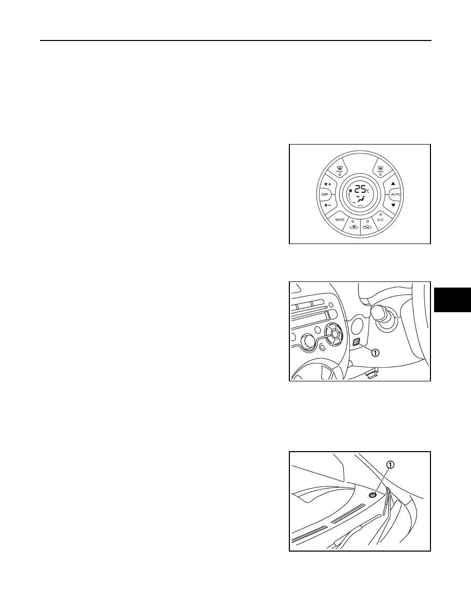
A/C Auto Amp.
INFOID:0000000006024058
• The A/C auto amp. has a built-in microcomputer which processes
information sent from various sensors needed for air conditioner
operation.
• The air mix door motor, mode door motor, intake door motor,
blower motor and the compressor are then controlled.
• The A/C auto amp. is unitized with control mechanism. Signal from
various switches are directly entered into A/C auto amp.
• Self-diagnosis functions are also built into A/C auto amp. to pro-
vide quick check of malfunctions in the auto air conditioner system.
In-vehicle Sensor
INFOID:0000000006024026
COMPONENT DESCRIPTION
• The in-vehicle sensor (1) is installed to the finisher.
• The in-vehicle sensor converts the interior air temperature of the
passenger room sucked by the aspirator detected with the ther-
mistor into the voltage, and the A/C auto amp. inputs this voltage.
INTERIOR AIR TEMPERATURE CORRECTION
• The A/C auto amp. inputs the temperature detected with the in-vehicle sensor as the interior air temperature.
• Perform the correction of the temperature detected with the in-vehicle sensor for each air conditioner control.
Sunload Sensor
INFOID:0000000006024032
COMPONENT DESCRIPTION
• The sunload sensor (1) is installed to the right side of instrument
panel assembly.
• The sunload sensor converts the sunload amount (illuminance)
into the current value with the photodiode. The A/C auto amp. cal-
culates this current value to the voltage and inputs it.
SUNLOAD AMOUNT CORRECTION
• The A/C auto amp. inputs the sunload amount detected with the sunload sensor.
JPIIA1743ZZ
JMIIA0692ZZ
JMIIA0694ZZ
HAC-12
< SYSTEM DESCRIPTION >
[AUTOMATIC AIR CONDITIONER]
COMPONENT PARTS
• Perform the correction of the sunload amount detected with the sunload sensor for each air conditioner con-
trol.
• When the sunload amount suddenly changes, for example when entering a tunnel, perform the correction so
that the recognition sunload amount of the A/C auto amp. changes slowly.
SYSTEM
HAC-13
< SYSTEM DESCRIPTION >
[AUTOMATIC AIR CONDITIONER]
C
D
E
F
G
H
J
K
L
M
A
B
HAC
N
O
P
SYSTEM
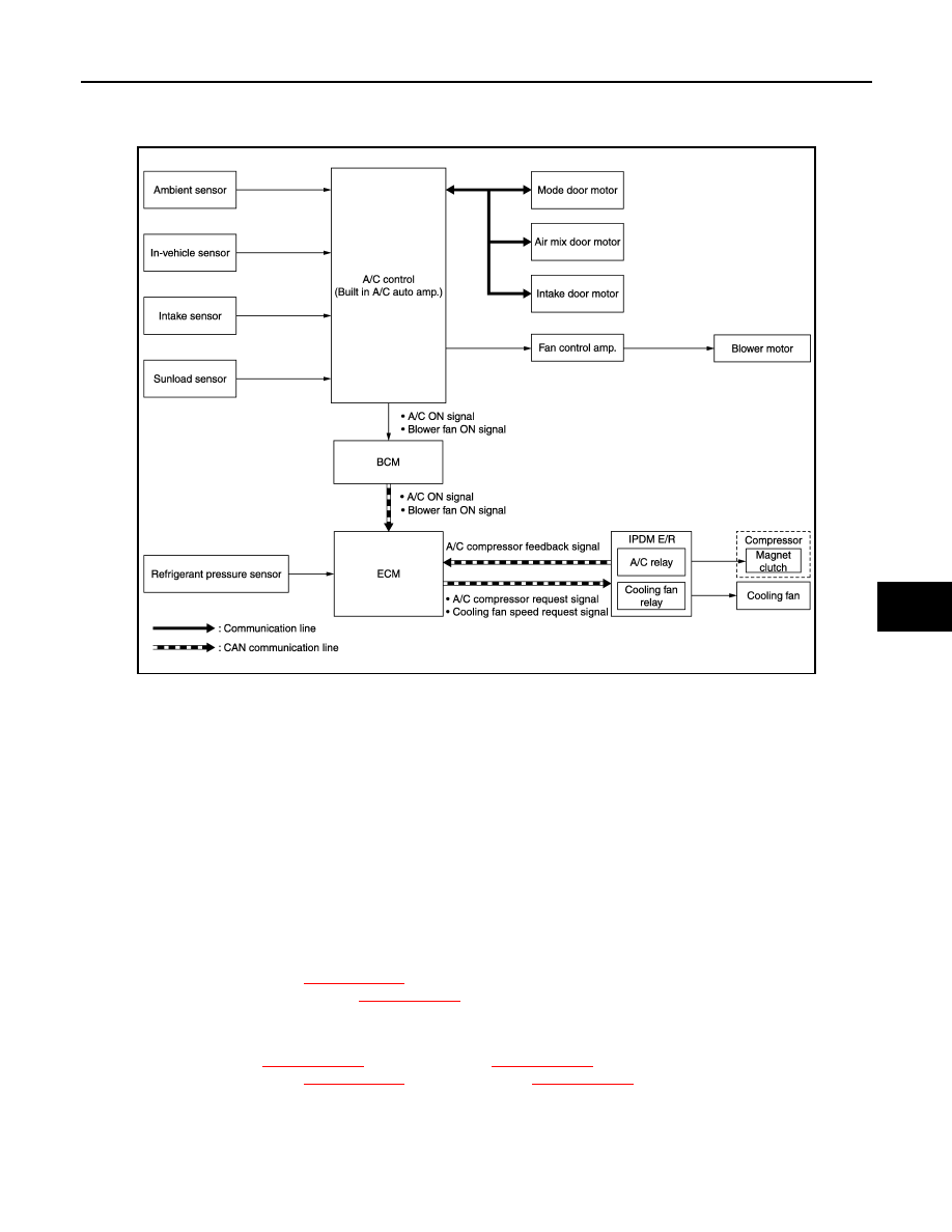
System Diagram
INFOID:0000000006024014
System Description
INFOID:0000000006043957
• Automatic air conditioner system is controlled by each function of A/C auto amp., ECM, BCM and IPDM E/R.
Control by A/C auto amp.
- Air outlet control
- Temperature control
- Air inlet control
- Air flow control
- Compressor control
- Door motor control (LCU communication control)
Control by BCM
- Compressor control
Control by ECM
- Cooling fan control. Refer to
XX-XX, "*****"
.
- Air conditioning cut control. Refer to
XX-XX, "*****"
.
- Compressor control
Control by IPDM E/R
- Relay control. Refer to
XX-XX, "*****"
(WITH I-KEY) or
XX-XX, "*****"
(WITHOUT I-KEY).
- Cooling fan control. Refer to
XX-XX, "*****"
(WITH I-KEY) or
XX-XX, "*****"
(WITHOUT I-KEY).
• Each A/C system can be operated by A/C controller (built-in A/C auto amp.).
Air Flow Control
INFOID:0000000006043958
DESCRIPTION
JMIIA0688GB
Нет комментариевНе стесняйтесь поделиться с нами вашим ценным мнением.
Текст