Nissan March K13. Manual — part 139
COMPONENT PARTS
EC-17
< SYSTEM DESCRIPTION >
[HR12DE (TYPE 1)]
C
D
E
F
G
H
I
J
K
L
M
A
EC
N
P
O
*: Not used for engine control system.
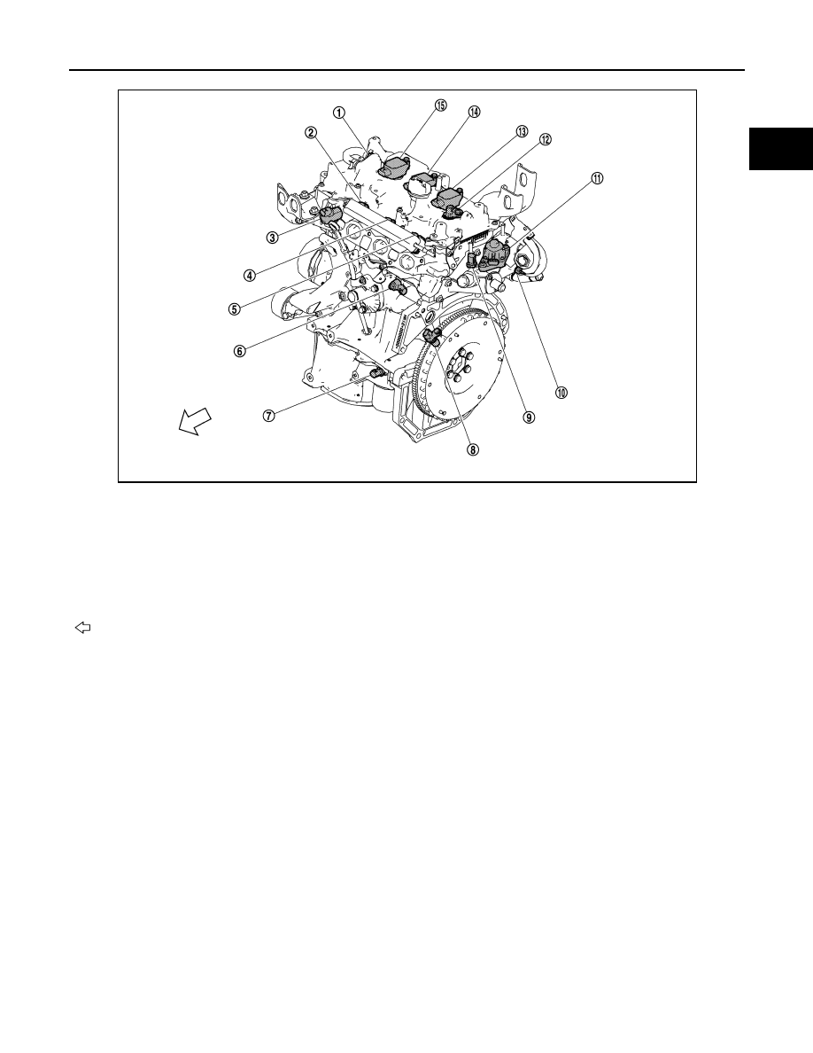
EXHAUST COMPARTMENT
JPBIA3223ZZ
1.
PCV valve
2.
Fuel injector No.1
3.
Intake valve timing control solenoid-
valve
4.
Fuel injector No.2
5.
Fuel injector No.3
6.
Knock sensor
7.
Engine oil temperature sensor
*
8.
Crankshaft position sensor (POS)
9.
Engine coolant temperature sensor
10.
EGR temperature sensor
11.
EGR volume control valve
12.
Camshaftposition sensor (PHASE)
13.
Ignition coil No.3 (with power transis-
tor)
14.
Ignition coil No.2 (with power transis-
tor)
15.
Ignition coil No.1 (with power transis-
tor)
:Vehicle front
EC-18
< SYSTEM DESCRIPTION >
[HR12DE (TYPE 1)]
COMPONENT PARTS
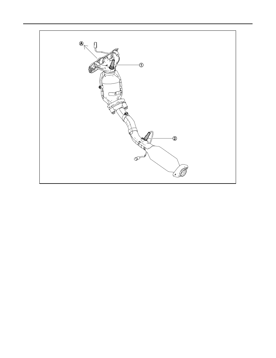
BODY COMPARTMENT
1.
A/F sensor 1
2.
Heated oxygen sensor 2
A.
To engine assembly
JPBIA3215ZZ
COMPONENT PARTS
EC-19
< SYSTEM DESCRIPTION >
[HR12DE (TYPE 1)]
C
D
E
F
G
H
I
J
K
L
M
A
EC
N
P
O
Component Description
INFOID:0000000005989668
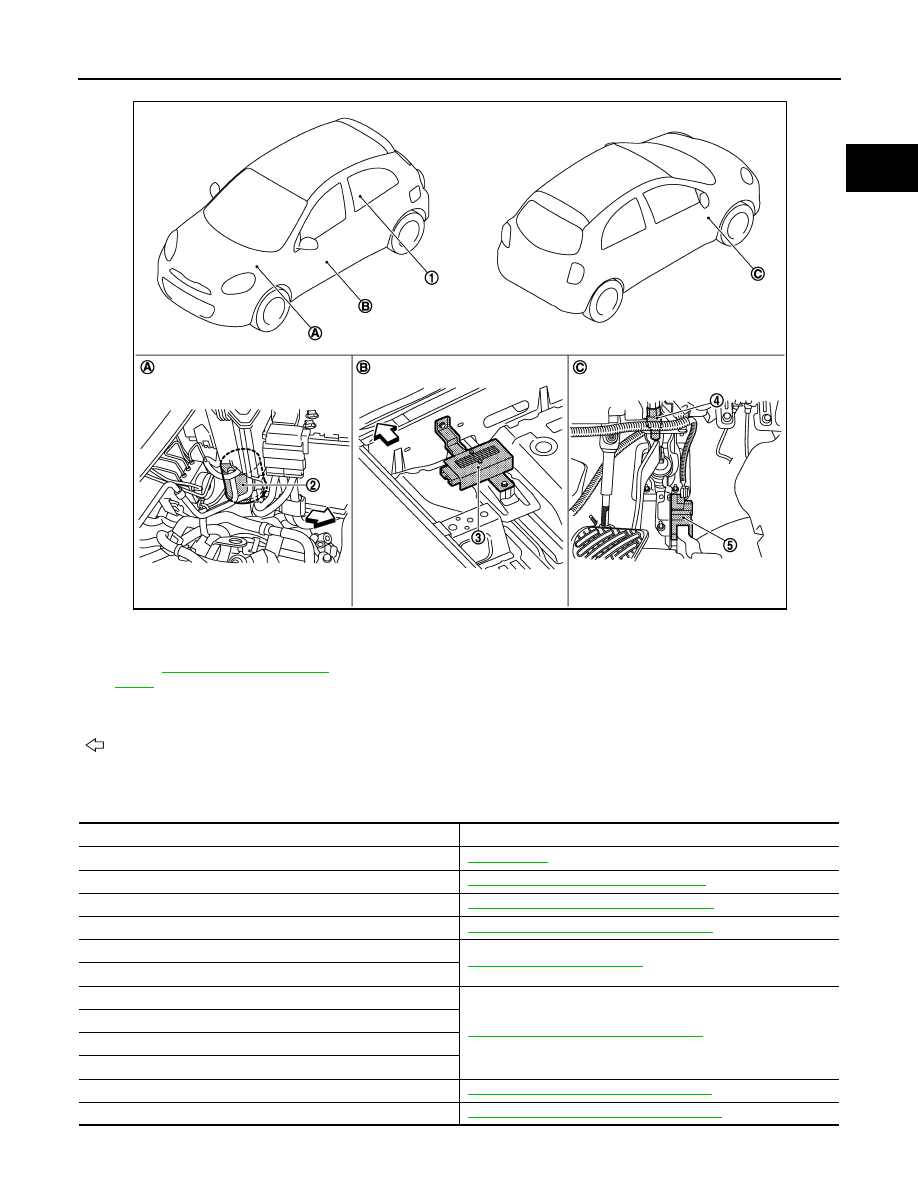
1.
Fuel pump (with fuel level sensor unit
and fuel pressure regulator)
Refer to
2.
EVAP canister
3.
Fuel pump control module (FPCM)
4.
Stop lamp switch
5.
Accelerator pedal position sensor
A.
Left side of engine room
B.
Under front seat (passenger side)
C.
Periphery of pedals
:
Vehicle front
JSBIA0354ZZ
Component
Reference
ECM
Malfunction indicator lamp
EC-20, "Malfunction Indicator Lamp (MIL)"
Ignition coil with power transistor
EC-21, "Ignition Coil With Power Transistor"
Accelerator pedal position sensor
EC-21, "Accelerator Pedal Position Sensor"
Mass air flow sensor
Intake air temperature sensor
Electric throttle control actuator
EC-22, "Electric Throttle Control Actuator"
Throttle control motor relay
Throttle control motor
Throttle position sensor
Crankshaft position sensor (POS)
EC-22, "Crankshaft Position Sensor (POS)"
Camshaft position sensor (PHASE)
EC-20
< SYSTEM DESCRIPTION >
[HR12DE (TYPE 1)]
COMPONENT PARTS
*: Not used for engine control system.
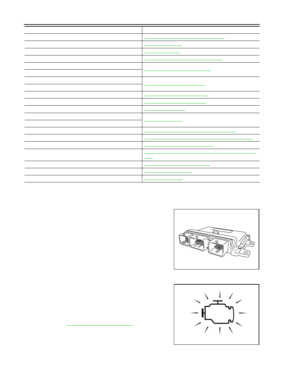
ECM
INFOID:0000000005991040
• ECM (Engine Control Module) controls the engine.
• ECM consists of a microcomputer and connectors for signal input
and output and for power supply.
• Battery voltage is supplied to the ECM even when the ignition
switch is turned OFF for the ECM memory function of the DTC
memory, the air-fuel ratio feedback compensation value memory,
the idle air volume learning value memory, etc.
Malfunction Indicator Lamp (MIL)
INFOID:0000000005991041
The Malfunction Indicator Lamp (MIL) is located on the combination
meter.
The MIL will illuminate when the ignition switch is turned ON without
the engine running. This is a bulb check.
When the engine is started, the MIL should turn off. If the MIL
remains illuminated, the on board diagnostic system has detected an
engine system malfunction.
For details, refer to
EC-45, "Diagnosis Description"
.
Engine coolant temperature sensor
EC-23, "Engine Coolant Temperature Sensor"
Fuel injector
Fuel pump
Fuel pump control module (FPCM)
EC-25, "Fuel Pump Control Module (FPCM)"
A/F sensor 1
EC-25, "Air Fuel Ratio (A/F) Sensor 1"
A/F sensor 1 heater
Heated oxygen sensor 2
EC-25, "Heated Oxygen Sensor 2"
Heated oxygen sensor 2 heater
EGR volume control valve
EC-26, "EGR Volume Control Valve"
EGR temperature sensor
EC-26, "EGR Temperature Sensor"
Knock sensor
Cooling fan control module
Cooling fan motor
Intake valve timing control solenoid valve
EC-28, "Intake Valve Timing Control Solenoid Valve"
EVAP canister purge volume control solenoid valve
EC-28, "EVAP Canister Purge Volume Control Solenoid Valve"
PCV valve
EC-15, "Positive Crankcase Ventilation"
Battery current sensor (with battery temperature sensor
*
)
EC-28, "Battery Current Sensor (With Battery Temperature Sen-
sor)"
Refrigerant pressure sensor
EC-29, "Refrigerant Pressure Sensor"
Stop lamp switch
Park/neutral position switch
Component
Reference
PBIA9222J
SAT652J
Нет комментариевНе стесняйтесь поделиться с нами вашим ценным мнением.
Текст