Nissan March K13. Manual — part 87
DOOR SWITCH
DLK-59
< DTC/CIRCUIT DIAGNOSIS >
[WITH INTELLIGENT KEY SYSTEM]
C
D
E
F
G
H
I
J
L
M
A
B
DLK
N
O
P
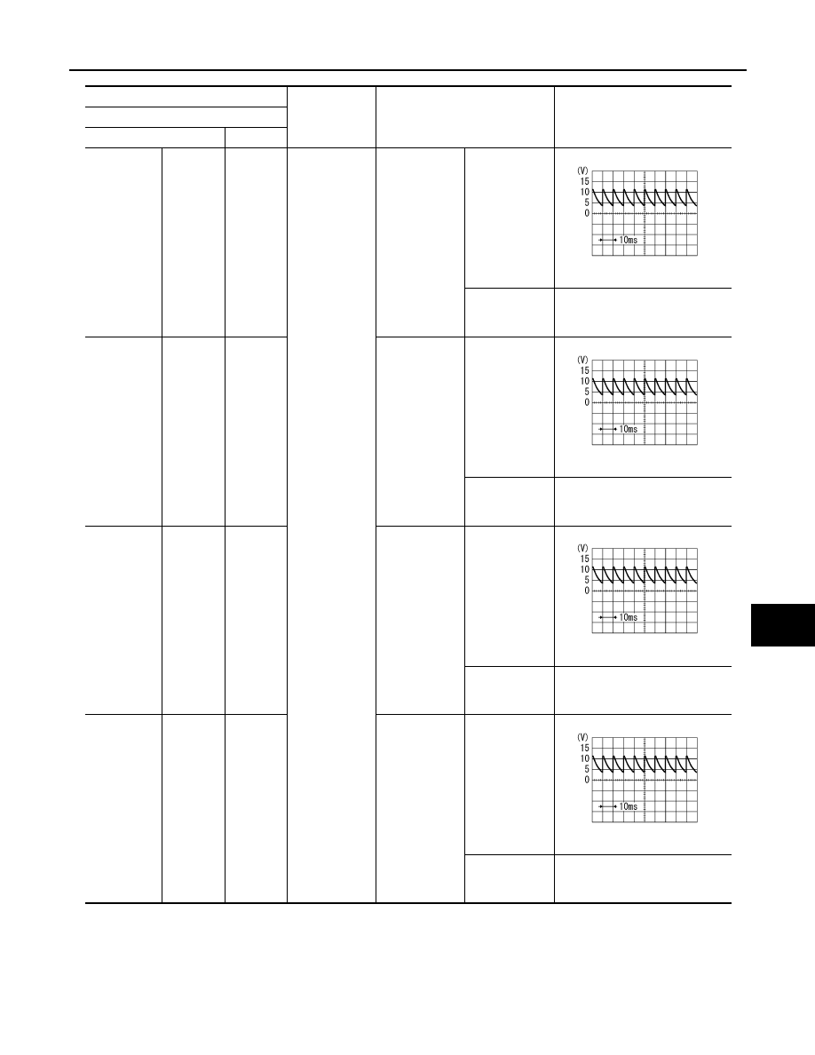
(+)
(–)
Condition
Signal
(Reference value)
Door switch
Connector
Terminal
Driver side
B35
3
Ground
Driver door
switch
OFF (When
driver door
closed)
7.0 - 8.0 V
ON (When driv-
er door
opened)
0 V
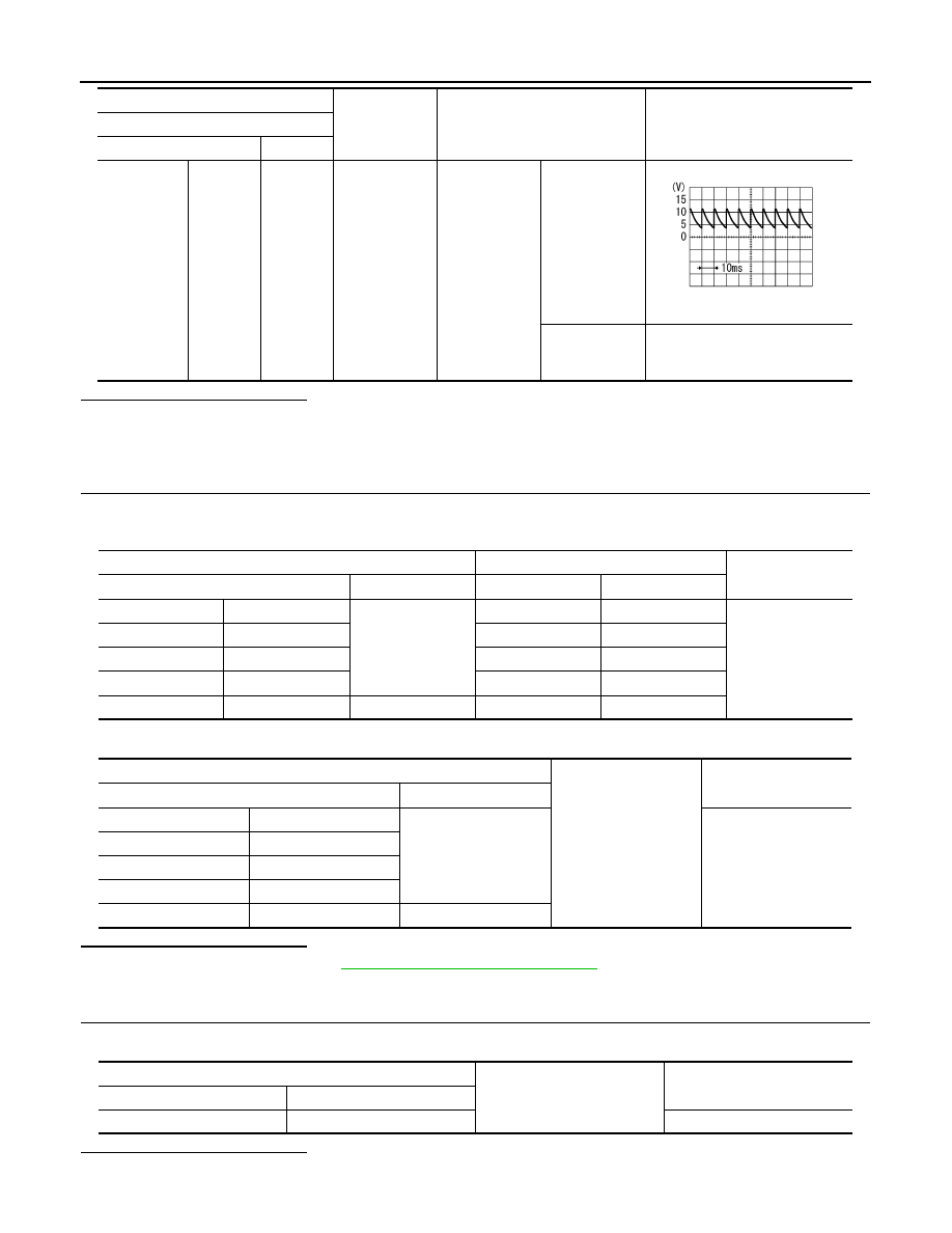
Passenger
side
B28
3
Passenger
door switch
OFF (When
passenger door
closed)
7.0 - 8.0 V
ON (When pas-
senger door
opened)
0 V
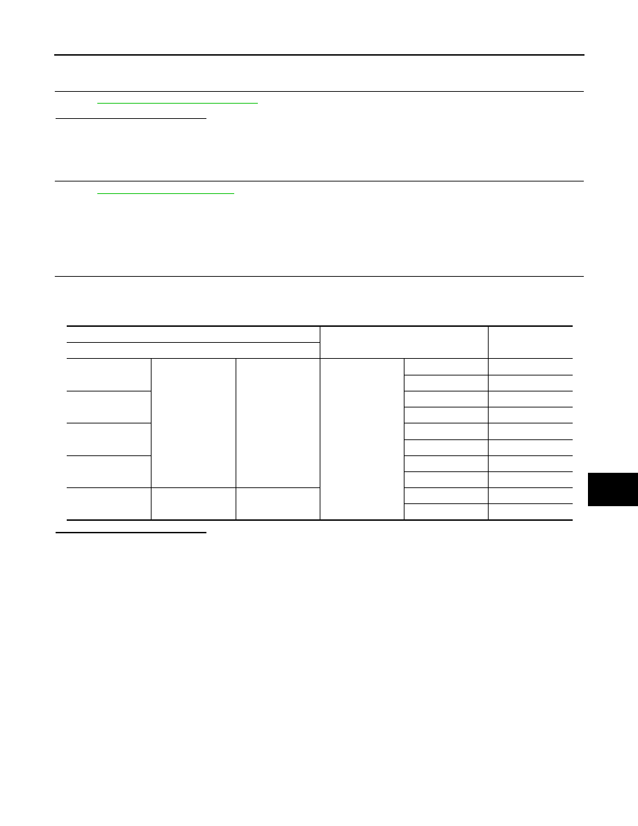
Rear LH
B71
3
Rear LH door
switch
OFF (When
rear LH door
closed)
7.0 - 8.0 V
ON (When rear
door LH
opened)
0 V
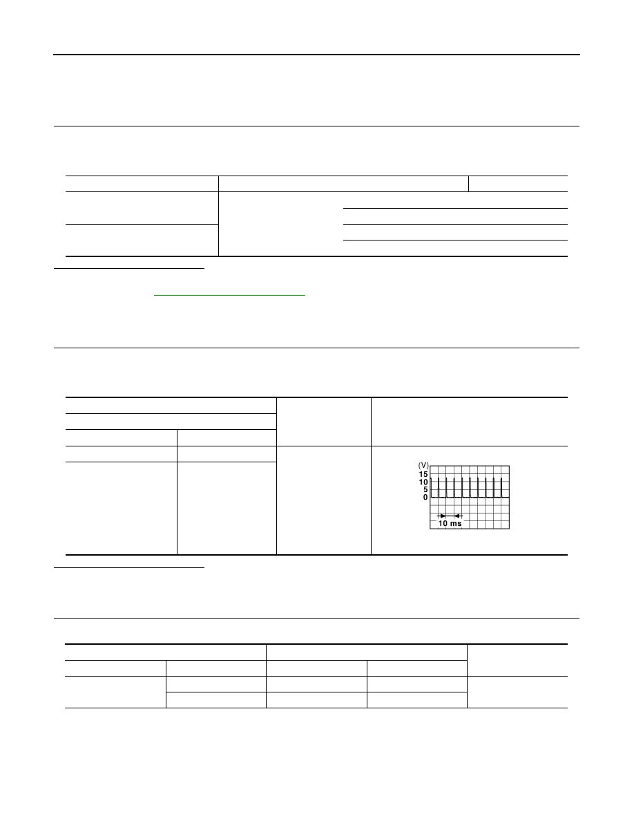
Rear RH
B53
3
Rear RH door
switch
OFF (When
rear RH door
closed)
7.0 - 8.0 V
ON (When rear
RH door
opened)
0 V
PKIB4960J
PKIB4960J
PKIB4960J
PKIB4960J
DLK-60
< DTC/CIRCUIT DIAGNOSIS >
[WITH INTELLIGENT KEY SYSTEM]
DOOR SWITCH
Is the inspection result normal?
YES-1 >> Back door: GO TO 3.
YES-1 >> Other doors: GO TO 4.
NO
>> GO TO 2.
2.
CHECK DOOR SWITCH CIRCUIT
1.
Disconnect BCM connector.
2.
Check continuity between door switch harness connector and BCM harness connector.
3.
Check continuity between door switch harness connector and ground.
Is the inspection result normal?
YES
>> Replace BCM. Refer to
BCS-57, "Removal and Installation"
NO
>> Repair or replace harness.
3.
CHECK BACK DOOR SWITCH GROUND CIRCUIT
Check continuity between back door switch harness connector and ground.
Is the inspection result normal?
YES
>> GO TO 4.
Back door
D70
1
Ground
Back door
switch
OFF
(When back
door closed)
9.5 - 10.0 V
ON
(When back
door opened)
0 V
(+)
(–)
Condition
Signal
(Reference value)
Door switch
Connector
Terminal
PKIB4960J
Door switch
BCM
Continuity
Connector
Terminal
Connector
Terminal
Driver side
B35
3
M69
47
Existed
Passenger side
B28
M68
12
Rear LH
B71
M69
48
Rear RH
B53
M68
13
Back door
D70
1
M69
43
Door switch
Ground
Continuity
Connector
Terminal
Driver side
B35
3
Not existed
Passenger side
B28
Rear LH
B71
Rear RH
B53
Back door
D70
1
Back door switch
Ground
Continuity
Connector
Terminal
D70
3
Existed
DOOR SWITCH
DLK-61
< DTC/CIRCUIT DIAGNOSIS >
[WITH INTELLIGENT KEY SYSTEM]
C
D
E
F
G
H
I
J
L
M
A
B
DLK
N
O
P
NO
>> Replace back door switch.
4.
CHECK DOOR SWITCH
DLK-61, "Component Inspection"
Is the inspection result normal?
YES
>> GO TO 5.
NO-1
>> Replace back door lock assembly. (back door)
NO-2
>> Replace malfunctioning door switch. (other door)
5.
CHECK INTERMITTENT INCIDENT
GI-33, "Intermittent Incident"
.
>> INSPECTION END
Component Inspection
INFOID:0000000005948847
1.
CHECK DOOR SWITCH
1.
Turn ignition switch OFF.
2.
Disconnect malfunctioning door switch connector.
3.
Check continuity between door switch terminals.
Is the inspection result normal?
YES
>> INSPECTION END
NO-1
>> Replace back door lock assembly. (back door)
NO-1
>> Replace malfunction door switch. (other door)
Door switch
Condition
Continuity
Terminal
Driver side
3
Ground part of door
switch
Door switch
Pressed
Not existed
Released
Existed
Passenger side
Pressed
Not existed
Released
Existed
Rear LH
Pressed
Not existed
Released
Existed
Rear RH
Pressed
Not existed
Released
Existed
Back door
1
3
Pressed
Not existed
Released
Existed
DLK-62
< DTC/CIRCUIT DIAGNOSIS >
[WITH INTELLIGENT KEY SYSTEM]
DOOR LOCK AND UNLOCK SWITCH
DOOR LOCK AND UNLOCK SWITCH
Component Function Check
INFOID:0000000005948849
1.
CHECK FUNCTION
1.
Select “DOOR LOCK” of “BCM” using CONSULT-III.
2.
Select “CDL LOCK SW”, “CDL UNLOCK SW” in “DATA MONITOR” mode.
3.
Check that the function operates normally according to the following conditions.
Is the inspection result normal?
YES
>> Door lock and unlock switch is OK.
NO
>> Refer to
.
Diagnosis Procedure
INFOID:0000000005948850
1.
CHECK DOOR LOCK AND UNLOCK SWITCH INPUT SIGNAL
1.
Turn ignition switch OFF.
2.
Disconnect power window main switch connector.
3.
Check signal between power window main switch harness connector and ground using oscilloscope.
Is the inspection result normal?
YES
>> GO TO 3.
NO
>> GO TO 2.
2.
CHECK DOOR LOCK AND UNLOCK SWITCH CIRCUIT
1.
Check continuity between BCM harness connector and power window main switch harness connector.
2.
Check continuity between BCM harness connector and ground.
Monitor item
Condition
Status
CDL LOCK SW
Door lock and unlock switch
LOCK
ON
UNLOCK
OFF
CDL UNLOCK SW
LOCK
OFF
UNLOCK
ON
(+)
(–)
Signal
(Reference value)
Power window main switch
Connector
Terminal
D5
6
Ground
1.0 - 1.5 V
D6
18
JPMIA0012GB
BCM
Power window main switch
Continuity
Connector
Terminal
Connector
Terminal
M69
45
D6
18
Existed
46
D5
6
Нет комментариевНе стесняйтесь поделиться с нами вашим ценным мнением.
Текст