Nissan March K13. Manual — part 238
P0134 HO2S1
EC-413
< DTC/CIRCUIT DIAGNOSIS >
[HR12DE (TYPE 2)]
C
D
E
F
G
H
I
J
K
L
M
A
EC
N
P
O
P0134 HO2S1
DTC Logic
INFOID:0000000005886527
DTC DETECTION LOGIC
Under the condition in which the heated oxygen sensor 1 signal is
not input, the ECM circuits will read a continuous approx. 0.3 V.
Therefore, for this diagnosis, the time that output voltage is within
200 to 400 mV range is monitored, and the diagnosis checks that
this time is not inordinately long.
DTC CONFIRMATION PROCEDURE
1.
INSPECTION START
Do you have CONSULT-III?
Do you have CONSULT-III?
YES
>> GO TO 2.
NO
>> GO TO 4.
2.
PRECONDITIONING
If DTC Confirmation Procedure has been previously conducted, always turn ignition switch OFF and wait at
least 10 seconds before conducting the next test.
TESTING CONDITION:
Always perform at a temperature above -10
°
C (14
°
F).
Before performing the following procedure, confirm that battery voltage is more than 11 V at idle.
>> GO TO 3.
3.
PERFORM DTC CONFIRMATION PROCEDURE
With CONSULT-III
1.
Start engine and warm it up to normal operating temperature.
2.
Stop engine and wait at least 10 seconds.
3.
Turn ignition switch ON and select “HO2S1 (B1) P0134” of “HO2S1” in “DTC WORK SUPPORT” mode
with CONSULT-III.
4.
Touch “START”.
5.
Start engine and let it idle for at least 3 minutes.
NOTE:
Never raise engine speed above 3,600 rpm after this step. If the engine speed limit is exceeded,
return to step 5.
6.
When the following conditions are met, “TESTING” will be displayed on the CONSULT-III screen. Maintain
the conditions continuously until “TESTING” changes to “COMPLETED”. (It will take approximately 40 to
50 seconds.)
CAUTION:
Always drive vehicle at a safe speed.
SEF237U
DTC No.
Trouble diagnosis name
DTC detecting condition
Possible cause
P0134
Heated oxygen sensor 1
circuit no activity detected
The voltage from the sensor is constantly
approx. 0.3 V.
• Harness or connectors
(The sensor circuit is open or shorted.)
• Heated oxygen sensor 1

EC-414
< DTC/CIRCUIT DIAGNOSIS >
[HR12DE (TYPE 2)]
P0134 HO2S1
If “TESTING” is not displayed after 5 minutes, retry from step 2.
7.
Touch “SELF-DIAG RESULTS”.
Which is displayed on COUSULT-III screen?
YES
>> INSPECTION END
NO
>> Go to
4.
PERFORM COMPONENT FUNCTION CHECK
Perform Component Function Check. Refer to
EC-414, "Component Function Check"
NOTE:
Use Component Function Check to check the overall function of heated oxygen sensor 1 circuit. During this
check, a 1st trip DTC might not be confirmed.
Is the inspection result normal?
YES
>> INSPECTION END
NO
>> Go to
Component Function Check
INFOID:0000000005886528
1.
PERFORM COMPONENT FUNCTION CHECK
Without CONSULT-III
1.
Start engine and warm it up to normal operating temperature.
2.
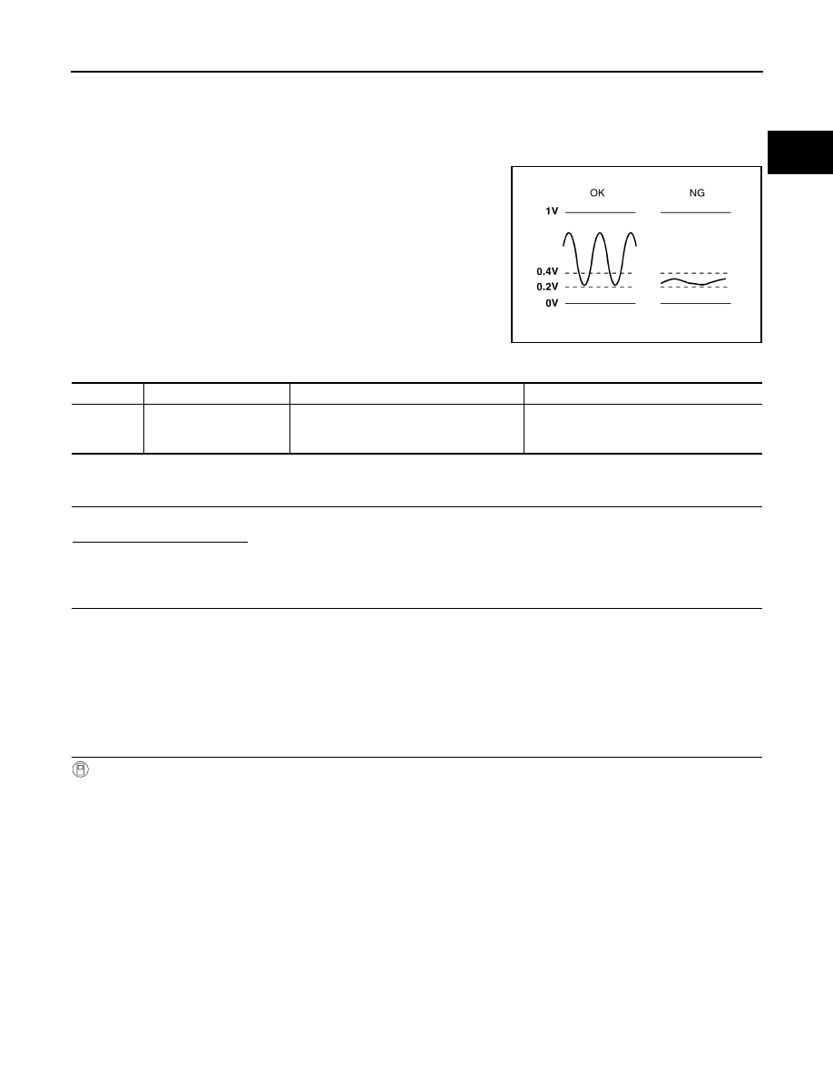
Check the voltage between ECM harness connector and ground under the following conditions.
Is the inspection result normal?
YES
>> INSPECTION END
NO
>> Go to
Diagnosis Procedure
INFOID:0000000005886529
1.
CHECK GROUND CONNECTION
1.
Turn ignition switch OFF.
2.
Check ground connection E38. Refer to Ground Inspection in
XX-XX, "*****"
.
Is the inspection result normal?
YES
>> GO TO 2.
NO
>> Repair or replace ground connection.
2.
CHECK HO2S1 GROUND CIRCUIT FOR OPEN AND SHORT
1.
Disconnect heated oxygen sensor 1 (HO2S1) harness connector.
2.
Disconnect ECM harness connector.
3.
Check harness continuity between HO2S1 harness connector and ECM harness connector.
ENG SPEED
1,500 - 3,100 rpm
VHCL SPEED SE
More than 64 km/h (40 MPH)
B/FUEL SCHDL
2.0 - 9.0 msec
Shift lever
Suitable position
ECM
Condition
Voltage
Connector
Terminal
+
−
F8
49
(HO2S1 signal)
56
Engine speed held at 2,000 rpm
constant under no load.
• The voltage dose not remain in the range of 0.2 to
0.4 V.
HO2S1
ECM
Continuity
Connector
Terminal
Connector
Terminal
F46
1
F8
56
Existed

P0134 HO2S1
EC-415
< DTC/CIRCUIT DIAGNOSIS >
[HR12DE (TYPE 2)]
C
D
E
F
G
H
I
J
K
L
M
A
EC
N
P
O
4.
Also check harness for short to ground and short to power.
Is inspection result normal?
YES
>> GO TO 3.
NO
>> Repair open circuit or short to ground or short to power in harness or connectors.
3.
CHECK HO2S1 INPUT SIGNAL CIRCUIT FOR OPEN AND SHORT
1.
Check harness continuity between HO2S1 harness connector and ECM harness connector.
2.
Check harness continuity between ECM harness connector 49 or HO2S1 harness connector and ground.
3.
Also check harness for short to power.
Is inspection result normal?
YES
>> GO TO 4.
NO
>> Repair open circuit or short to ground or short to power in harness or connectors.
4.
CHECK HEATED OXYGEN SENSOR 1
Refer to
XX-XX, "*****"
.
Is inspection result normal?
YES
>> GO TO 5.
NO
>> Replace heated oxygen sensor 1.
5.
CHECK INTERMITTENT INCIDENT
Refer to
XX-XX, "*****"
.
>> INSPECTION END
Component Inspection
INFOID:0000000005886530
1.
INSPECTION START
Do you have CONSULT-III?
Do you have CONSULT-III?
YES
>> GO TO 2.
NO
>> GO TO 3.
2.
CHECK HEATED OXYGEN SENSOR 1
With CONSULT-III
1.
Start engine and warm it up to normal operating temperature.
2.
Set “POST TRIGGER” to 100% in “DATA MONITOR” mode with CONSULT-III.
3.
Select “HO2S1 (B1)” and “HO2S1 MNTR (B1)”.
4.
Hold engine speed at 2,000 rpm under no load during the following steps.
5.
Touch “RECORD” on CONSULT-III screen.
HO2S1
ECM
Continuity
Connector
Terminal
Connector
Terminal
F46
4
F8
49
Existed
HO2S1
ECM
Ground
Continuity
Connector
Terminal
Connector
Terminal
F46
4
F8
49
Ground
Not existed
EC-416
< DTC/CIRCUIT DIAGNOSIS >
[HR12DE (TYPE 2)]
P0134 HO2S1
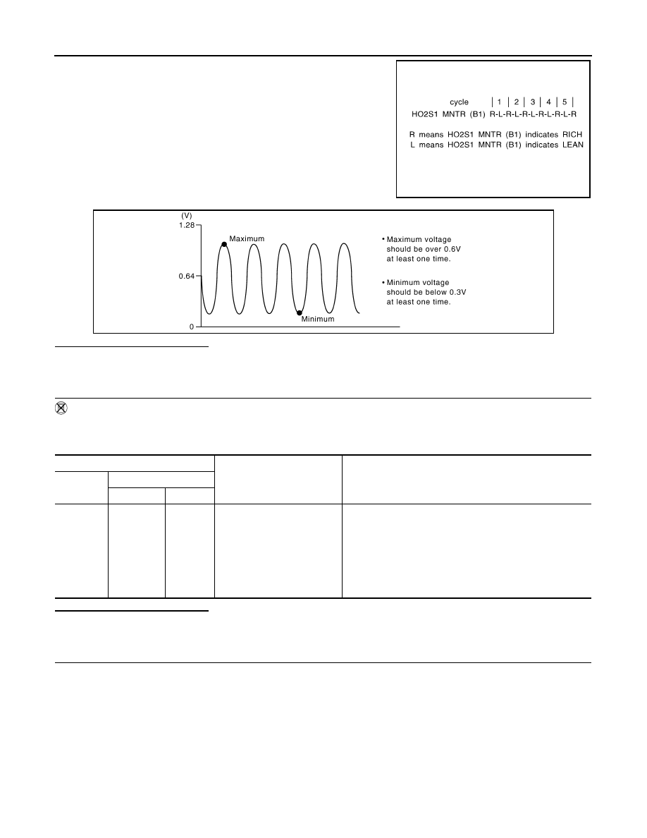
6.
Check the following.
-
“HO2S1 MNTR (B1)” in “DATA MONITOR” mode changes from
“RICH” to “LEAN” to “RICH” more than 5 times in 10 seconds.
5 times (cycles) are counted as shown in the figure.
-
“HO2S1 (B1)” voltage goes above 0.6 V at least once.
-
“HO2S1 (B1)” voltage goes below 0.3 V at least once.
-
“HO2S1 (B1)” voltage never exceeds 1.0 V.
Is the inspection result normal?
YES
>> INSPECTION END
NO
>> GO TO 4.
3.
CHECK HEATED OXYGEN SENSOR 1
Without CONSULT-III
1.
Start engine and warm it up to normal operating temperature.
2.
Check the voltage between ECM harness connector and ground under the following condition.
Is the inspection result normal?
YES
>> INSPECTION END
NO
>> GO TO 4.
4.
REPLACE HEATED OXYGEN SENSOR 1
Replace heated oxygen sensor 1.
CAUTION:
• Discard any heated oxygen sensor which has been dropped from a height of more than 0.5 m (19.7
in) onto a hard surface such as a concrete floor; use a new one.
• Before installing new heated oxygen sensor, clean exhaust system threads using Oxygen Sensor
Thread Cleaner (commercial service tool) and approved Anti-seize Lubricant (commercial service
tool).
>> INSPECTION END
SEF217YA
JMBIA0352ZZ
ECM
Condition
Voltage
Connector
Terminal
+
−
F8
49
(HO2S1
signal)
56
Engine speed held at 2,000
rpm constant under no load.
• The voltage fluctuates between 0 to 0.3 V and 0.6 to 1.0 V
more than 5 times within 10 seconds.
• The maximum voltage is over 0.6 V at least 1 time.
• The minimum voltage is below 0.3 V at least 1 time.
• The voltage never exceeds 1.0 V.
1 time: 0 - 0.3 V
→
0.6 - 1.0 V
→
0 - 0.3 V
2 times: 0 - 0.3 V
→
0.6 - 1.0 V
→
0 - 0.3 V
→
0.6 - 1.0 V
→
0 - 0.3 V
Нет комментариевНе стесняйтесь поделиться с нами вашим ценным мнением.
Текст