Nissan March K13. Manual — part 294
EXL-2
CONSULT-III Function (IPDM E/R) . . . . . ....
ECU DIAGNOSIS INFORMATION . . . ..
BCM, IPDM E/R . . . . . . . . . . . . .
List of ECU Reference . . . . . . . . . . ....
WIRING DIAGRAM . . . . . . . . . .
HEADLAMP SYSTEM . . . . . . . . . ...
Wiring Diagram - HEADLAMP - . . . . . . . ..
FRONT FOG LAMP SYSTEM . . . . . . ...
Wiring Diagram - FRONT FOG LAMP - . . . . ..
TURN SIGNAL AND HAZARD WARNING
LAMP SYSTEM . . . . . . . . . . . . .
Wiring Diagram - TURN AND HAZARD WARN-
ING LAMPS - . . . . . . . . . . . . . . ..
PARKING, LICENSE PLATE, SIDE MARKER
AND TAIL LAMPS SYSTEM . . . . . . . .
Wiring Diagram - PARKING, LICENSE PLATE,
SIDE MARKER AND TAIL LAMPS - . . . . . ..
STOP LAMP . . . . . . . . . . . . . ..
Wiring Diagram - STOP LAMP - . . . . . . . .
BACK-UP LAMP . . . . . . . . . . . .
Wiring Diagram - BACK-UP LAMP - . . . . . ...
BASIC INSPECTION . . . . . . . . ...
DIAGNOSIS AND REPAIR WORKFLOW . . .
Work Flow . . . . . . . . . . . . . . . ...
DTC/CIRCUIT DIAGNOSIS . . . . . . .
EXTERIOR LAMP FUSE . . . . . . . . ...
Diagnosis Procedure . . . . . . . . . . . ..
HEADLAMP (HI) CIRCUIT . . . . . . . .
Component Function Check . . . . . . . . ...
Diagnosis Procedure . . . . . . . . . . . ..
HEADLAMP (LO) CIRCUIT . . . . . . . ...
Component Function Check . . . . . . . . ...
Diagnosis Procedure . . . . . . . . . . . ..
FRONT FOG LAMP CIRCUIT . . . . . . ...
Component Function Check . . . . . . . . ...
Diagnosis Procedure . . . . . . . . . . . ..
PARKING LAMP CIRCUIT . . . . . . . .
Component Function Check . . . . . . . . ...
Diagnosis Procedure . . . . . . . . . . . ..
TURN SIGNAL LAMP CIRCUIT . . . . . .
Component Function Check . . . . . . . . ...
Diagnosis Procedure . . . . . . . . . . . ..
HAZARD SWITCH . . . . . . . . . . . .
Component Function Check . . . . . . . . ...
Diagnosis Procedure . . . . . . . . . . . ...
TAIL LAMP CIRCUIT . . . . . . . . . .
Component Function Check . . . . . . . . ...
Diagnosis Procedure . . . . . . . . . . . ...
LICENSE PLATE LAMP CIRCUIT . . . . .
Component Function Check . . . . . . . . ...
Diagnosis Procedure . . . . . . . . . . . ...
FRONT FOG LAMP RELAY . . . . . . . ..
Diagnosis Procedure . . . . . . . . . . . ...
Component Inspection . . . . . . . . . . .
SYMPTOM DIAGNOSIS . . . . . . .
EXTERIOR LIGHTING SYSTEM SYMPTOMS ...
Symptom Table . . . . . . . . . . . . . ...
BOTH SIDE HEADLAMPS (HI) ARE NOT
TURNED ON . . . . . . . . . . . . . ..
Description . . . . . . . . . . . . . . . ..
Diagnosis Procedure . . . . . . . . . . . ...
BOTH SIDE HEADLAMPS (LO) ARE NOT
TURNED ON . . . . . . . . . . . . . ..
Description . . . . . . . . . . . . . . . ..
Diagnosis Procedure . . . . . . . . . . . ...
PARKING, LICENSE PLATE AND TAIL
LAMPS ARE NOT TURNED ON . . . . . ...
Description . . . . . . . . . . . . . . . ..
Diagnosis Procedure . . . . . . . . . . . ...
BOTH SIDE FRONT FOG LAMPS ARE NOT
TURNED ON . . . . . . . . . . . . . ..
Description . . . . . . . . . . . . . . . ..
Diagnosis Procedure . . . . . . . . . . . ...
PERIODIC MAINTENANCE . . . . . ...
HEADLAMP AIMING ADJUSTMENT . . . ...
Description . . . . . . . . . . . . . . . ..
Aiming Adjustment Procedure . . . . . . . .
FRONT FOG LAMP AIMING ADJUSTMENT ...
Description . . . . . . . . . . . . . . . ..
Aiming Adjustment Procedure . . . . . . . .
REMOVAL AND INSTALLATION . . . ..
FRONT COMBINATION LAMP . . . . . . .
Exploded View . . . . . . . . . . . . . .
Removal and Installation . . . . . . . . . . .
Replacement . . . . . . . . . . . . . . ...
Disassembly and Assembly . . . . . . . . .
FRONT FOG LAMP . . . . . . . . . . ...
Exploded View . . . . . . . . . . . . . .
Removal and Installation . . . . . . . . . . .
EXL-3
C
D
E
F
G
H
I
J
K
M
A
B
EXL
N
O
P
LIGHTING & TURN SIGNAL SWITCH . . . ..
Exploded View . . . . . . . . . . . . . .
SIDE TURN SIGNAL LAMP . . . . . . . ...
Exploded View . . . . . . . . . . . . . .
Removal and Installation . . . . . . . . . . .
Replacement . . . . . . . . . . . . . . ...
HAZARD SWITCH . . . . . . . . . . . ..
Exploded View . . . . . . . . . . . . . .
Removal and Installation . . . . . . . . . . .
REAR COMBINATION LAMP . . . . . . .
Exploded View . . . . . . . . . . . . . .
Removal and Installation . . . . . . . . . . .
Replacement . . . . . . . . . . . . . . ...
HIGH-MOUNTED STOP LAMP . . . . . ..
Exploded View . . . . . . . . . . . . . ...
Removal and Installation . . . . . . . . . ...
Replacement . . . . . . . . . . . . . . .
LICENSE PLATE LAMP . . . . . . . . .
Exploded View . . . . . . . . . . . . . ...
Removal and Installation . . . . . . . . . ...
Replacement . . . . . . . . . . . . . . .
SERVICE DATA AND SPECIFICATIONS
(SDS) . . . . . . . . . . . . . . ..
SERVICE DATA AND SPECIFICATIONS
(SDS) . . . . . . . . . . . . . . . ...
EXL-4
< PRECAUTION >
PRECAUTIONS
PRECAUTION
PRECAUTIONS
Precaution for Supplemental Restraint System (SRS) "AIR BAG" and "SEAT BELT
PRE-TENSIONER"
INFOID:0000000005912264
The Supplemental Restraint System such as “AIR BAG” and “SEAT BELT PRE-TENSIONER”, used along
with a front seat belt, helps to reduce the risk or severity of injury to the driver and front passenger for certain
types of collision. This system includes seat belt switch inputs and dual stage front air bag modules. The SRS
system uses the seat belt switches to determine the front air bag deployment, and may only deploy one front
air bag, depending on the severity of a collision and whether the front occupants are belted or unbelted.
Information necessary to service the system safely is included in the “SRS AIR BAG” and “SEAT BELT” of this
Service Manual.
WARNING:
• To avoid rendering the SRS inoperative, which could increase the risk of personal injury or death in
the event of a collision that would result in air bag inflation, all maintenance must be performed by
an authorized NISSAN/INFINITI dealer.
• Improper maintenance, including incorrect removal and installation of the SRS, can lead to personal
injury caused by unintentional activation of the system. For removal of Spiral Cable and Air Bag
Module, see the “SRS AIR BAG”.
• Do not use electrical test equipment on any circuit related to the SRS unless instructed to in this
Service Manual. SRS wiring harnesses can be identified by yellow and/or orange harnesses or har-
ness connectors.
PRECAUTIONS WHEN USING POWER TOOLS (AIR OR ELECTRIC) AND HAMMERS
WARNING:
• When working near the Air Bag Diagnosis Sensor Unit or other Air Bag System sensors with the
ignition ON or engine running, DO NOT use air or electric power tools or strike near the sensor(s)
with a hammer. Heavy vibration could activate the sensor(s) and deploy the air bag(s), possibly
causing serious injury.
• When using air or electric power tools or hammers, always switch the ignition OFF, disconnect the
battery, and wait at least 3 minutes before performing any service.
COMPONENT PARTS
EXL-5
< SYSTEM DESCRIPTION >
C
D
E
F
G
H
I
J
K
M
A
B
EXL
N
O
P
SYSTEM DESCRIPTION
COMPONENT PARTS
EXTERIOR LIGHTING SYSTEM
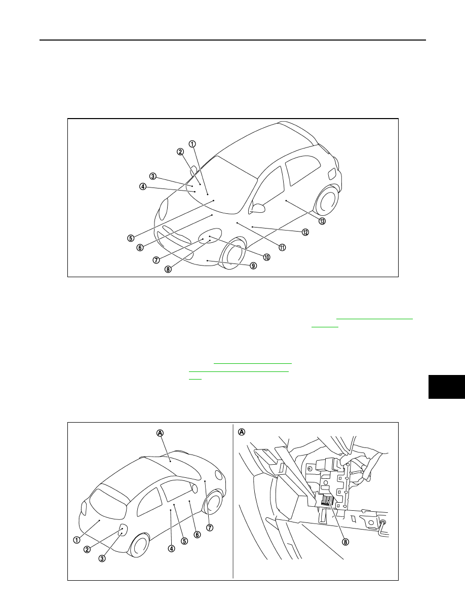
EXTERIOR LIGHTING SYSTEM : Component Parts Location
INFOID:0000000005912270
1.
Push switch
(With Intelligent Key)
2.
Key switch
(Without Intelligent Key)
3.
Combination switch
4.
Combination meter
5.
Hazard switch
6.
IPDM E/R
Refer to
7.
Front turn signal lamp
8.
Parking lamp
9.
Front fog lamp
(With Intelligent Key)
10. Headlamp
11.
BCM
Refer to
SYSTEM : Component Parts Loca-
tion"
12. Side turn signal lamp
13. Front door request switch (passen-
ger side)
(With Intelligent Key)
JMLIA0929ZZ
JMLIA0930ZZ
Нет комментариевНе стесняйтесь поделиться с нами вашим ценным мнением.
Текст