Nissan March K13. Manual — part 666
WCS
COMBINATION METER
WCS-25
< ECU DIAGNOSIS INFORMATION >
C
D
E
F
G
H
I
J
K
L
M
B
A
O
P
NOTE:
Some items are not available according to vehicle specification.
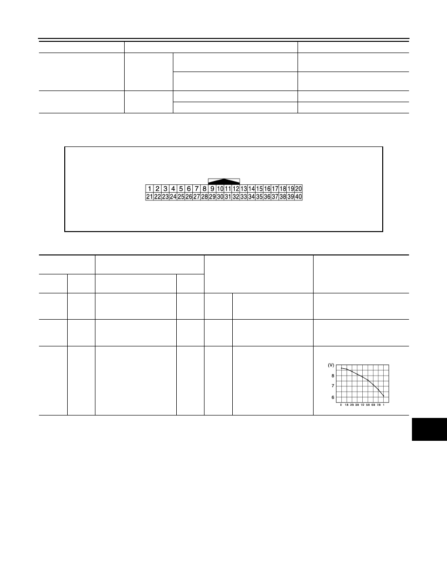
TERMINAL LAYOUT
PHYSICAL VALUES
FUEL LOW SIG
Ignition switch
ON
Low fuel warning displayed
Dummy cross-reference("XX-XX")
On
Low fuel warning not displayed
Dummy cross-reference("XX-XX")
Off
BUZZER
Ignition switch
ON
Buzzer ON
On
Buzzer OFF
Off
Monitor Item
Condition
Value/Status
JPNIA0968GB
Terminal No.
(Wire color)
Description
Condition
Value
(Approx.)
+
–
Signal name
Input/
Output
1
(R)
Ground
Battery power supply
Input
Ignition
switch
OFF
—
Battery voltage
3
(GR)
Ground
Ignition signal
Input
Ignition
switch
ON
—
Battery voltage
4
(W)
26
(GR)
Fuel level sensor signal
Input
Ignition
switch
ON
—
JSNIA2927ZZ
WCS-26
< ECU DIAGNOSIS INFORMATION >
COMBINATION METER
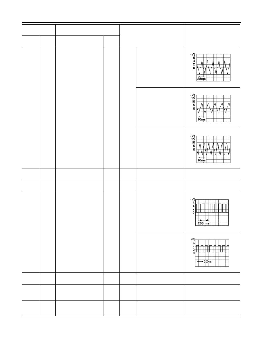
6
(L)
25
(B)
Vehicle speed sensor sig-
nal
Input
Ignition
switch
ON
Speedometer operated
[When vehicle speed is ap-
prox. 20 km/h (12.5 MPH)]
Speedometer operated
[When vehicle speed is ap-
prox. 40 km/h (25 MPH)]
Speedometer operated
[When vehicle speed is ap-
prox. 60 km/h (37.5 MPH)]
8
(L)
—
CAN-H
—
—
—
—
10
(P)
—
CAN-L
—
—
—
—
14
(G)
Ground
Engine coolant tempera-
ture signal
Output
Ignition
switch
ON
Engine idling [Approximate-
ly 20
°
C (68
°
F)]
Engine idling [Approximate-
ly 80
°
C (176
°
F)]
0 V
15
*
(GR)
—
—
—
—
—
—
21
(B)
Ground
Ground
—
Ignition
switch
ON
—
0 V
22
(B)
Ground
Ground
—
Ignition
switch
ON
—
0 V
Terminal No.
(Wire color)
Description
Condition
Value
(Approx.)
+
–
Signal name
Input/
Output
JSNIA3084ZZ
JSNIA3085ZZ
JSNIA3086ZZ
PKID0590E
SKIB3651J
WCS
COMBINATION METER
WCS-27
< ECU DIAGNOSIS INFORMATION >
C
D
E
F
G
H
I
J
K
L
M
B
A
O
P
*: This harness is not used.
Fail-Safe
INFOID:0000000005904786
FAIL-SAFE
The combination meter activates the fail-safe control if CAN communication with each unit is malfunctioning.
23
(B/W)
Ground
Ground
—
Ignition
switch
ON
—
0 V
28
(P)
Ground
Overdrive control switch
signal
Input
Ignition
switch
ON
While pressing the over-
drive control switch.
0 V
Other than the above
12 V
31
(G)
Ground
Security signal
Input
Ignition
switch
ON
Security warning lamp ON
0 V
Security warning lamp OFF
12 V
32
(V)
Ground
Air bag signal
Input
Ignition
switch
ON
Air bag warning lamp
ON
6 V
Air bag warning lamp
OFF
0 V
35
(Y)
Ground
Alternator signal
Input
Ignition
switch
ON
Charge warning lamp ON
2 V
Charge warning lamp OFF
12 V
36
(LG)
Ground
Brake fluid level switch sig-
nal
Input
Ignition
switch
ON
Brake fluid level is normal
12 V
Brake fluid level is less than
low level
0 V
37
(SB)
Ground
Parking brake switch signal
Input
Ignition
switch
ON
Parking brake applied.
0 V
Parking brake released.
12 V
Terminal No.
(Wire color)
Description
Condition
Value
(Approx.)
+
–
Signal name
Input/
Output
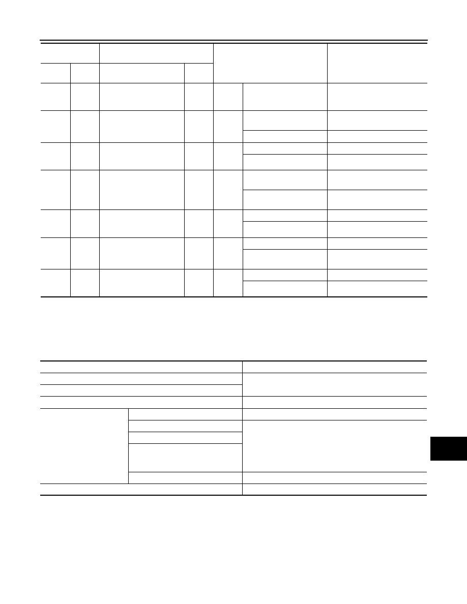
Function
Specifications
Speedometer (A/T models)
Reset to zero by suspending communication.
Tachometer
Illumination control
When suspending communication, changes to nighttime mode.
Information display
Shift position indicator
The indicator turns OFF by suspending communication.
Instantaneous fuel consumption
• When reception time of an abnormal signal is 2 seconds or
less, the last received datum is used for calculation to indi-
cate the result.
• When reception time of an abnormal signal is more than two
seconds, the last result calculated during normal condition is
indicated.
Average fuel consumption
Possible driving distance
Engine start operation indicator
The indicator turns OFF by suspending communication.
Buzzer
The buzzer turns off by suspending communication.
WCS-28
< ECU DIAGNOSIS INFORMATION >
COMBINATION METER
DTC Index
INFOID:0000000005904787
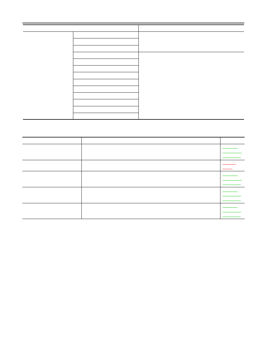
Warning lamp/indicator lamp
ABS warning lamp
The lamp turns ON by suspending communication.
EPS warning lamp
Brake warning lamp (With ABS)
High water temperature warning lamp
The lamp turns OFF by suspending communication.
Malfunction indicator lamp
High beam indicator lamp
Turn signal indicator lamp
Front fog lamp indicator lamp
Door warning lamp
Shift P warning lamp
Key warning lamp
Oil pressure warning lamp
OD OFF indicator lamp
Function
Specifications
Display contents of CONSULT-III
Diagnostic item is detected when...
Refer to
CAN COMM CIRCUIT
[U1000]
When combination meter is not transmitting or receiving CAN communication signal
for 2 seconds or more.
CONTROL UNIT (CAN)
[U1010]
When detecting error during the initial diagnosis of the CAN controller of combina-
tion meter.
XX-XX,
"*****"
VEHICLE SPEED
[B2205]
The abnormal vehicle speed signal is input from the ABS actuator and electric unit
(control unit) for 2 seconds or more.
ENGINE SPEED
[B2267]
If ECM continuously transmits abnormal engine speed signals for 2 seconds or
more.
WATER TEMP
[B2268]
If ECM continuously transmits abnormal engine coolant temperature signals for 60
seconds or more.
Нет комментариевНе стесняйтесь поделиться с нами вашим ценным мнением.
Текст