Nissan March K13. Manual — part 198
P1554 BATTERY CURRENT SENSOR
EC-253
< DTC/CIRCUIT DIAGNOSIS >
[HR12DE (TYPE 1)]
C
D
E
F
G
H
I
J
K
L
M
A
EC
N
P
O
6.
REPLACE ACCELERATOR PEDAL ASSEMBLY
1.
Replace accelerator pedal assembly.
2.
Go to
XX-XX, "*****"
.
>> INSPECTION END
7.
CHECK BATTERY CURRENT SENSOR GROUND CIRCUIT FOR OPEN AND SHORT
1.
Turn ignition switch OFF.
2.
Disconnect ECM harness connector.
3.
Check the continuity between battery current sensor harness connector and ECM harness connector.
4.
Also check harness for short to ground and short to power.
Is the inspection result normal?
YES
>> GO TO 8.
NO
>> Repair open circuit, short to ground or short to power in harness or connectors.
8.
CHECK BATTERY CURRENT SENSOR INPUT SIGNAL CIRCUIT FOR OPEN AND SHORT
1.
Check the continuity between battery current sensor harness connector and ECM harness connector.
2.
Also check harness for short to ground and short to power.
Is the inspection result normal?
YES
>> GO TO 9.
NO
>> Repair open circuit, short to ground or short to power in harness or connectors.
9.
CHECK BATTERY CURRENT SENSOR
Check battery current sensor. Refer to
EC-253, "Component Inspection"
.
Is the inspection result normal?
YES
>> GO TO 10.
NO
>> Replace battery negative cable assembly.
10.
CHECK INTERMITTENT INCIDENT
Check intermittent incident. Refer to
GI-33, "Intermittent Incident"
.
>> Repair or replace malfunctioning part.
Component Inspection
INFOID:0000000006057773
1.
CHECK BATTERY CURRENT SENSOR
1.
Turn ignition switch OFF.
2.
Reconnect harness connectors disconnected.
Battery current sensor
ECM
Continuity
Connector
Terminal
Connector
Terminal
F53
3
F16
68
Existed
Battery current sensor
ECM
Continuity
Connector
Terminal
Connector
Terminal
F53
4
F16
58
Existed
EC-254
< DTC/CIRCUIT DIAGNOSIS >
[HR12DE (TYPE 1)]
P1554 BATTERY CURRENT SENSOR
3.
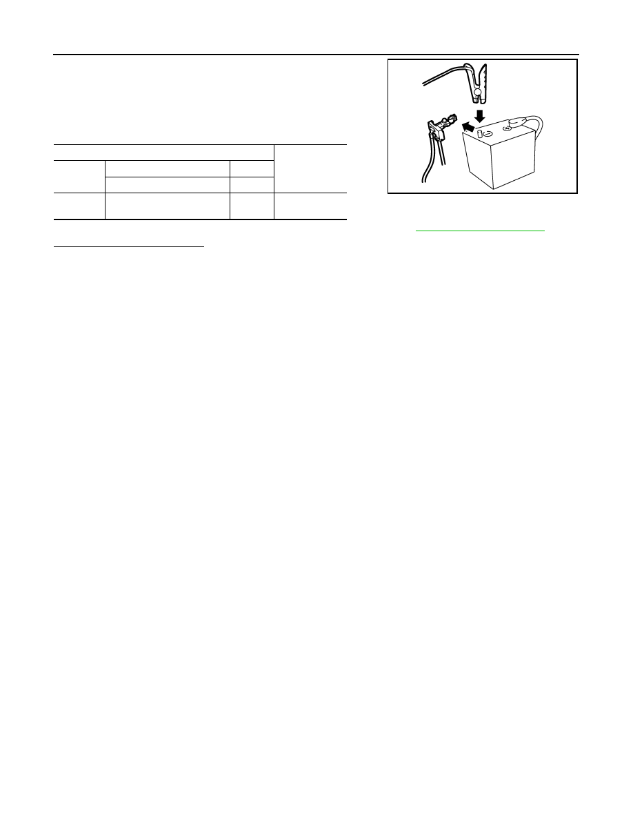
Disconnect battery negative cable.
4.
Install jumper cable between battery negative terminal and body
ground.
5.
Turn ignition switch ON.
6.
Check the voltage between ECM harness connector terminals
under the following conditions.
Before measuring the terminal voltage, confirm that the battery is fully charged. Refer to
PG-130, "How to Handle Battery"
.
Is the inspection result normal?
YES
>> INSPECTION END
NO
>> Replace battery negative cable assembly.
ECM
Voltage (V)
Connector
+
–
Terminal
Terminal
F16
58
(Battery current sensor signal)
68
Approx. 2.5
JPBIA3287ZZ

P1805 BRAKE SWITCH
EC-255
< DTC/CIRCUIT DIAGNOSIS >
[HR12DE (TYPE 1)]
C
D
E
F
G
H
I
J
K
L
M
A
EC
N
P
O
P1805 BRAKE SWITCH
DTC Logic
INFOID:0000000005989344
DTC DETECTION LOGIC
DTC CONFIRMATION PROCEDURE
1.
PERFORM DTC CONFIRMATION PROCEDURE
1.
Turn ignition switch ON.
2.
Fully depress the brake pedal for at least 5 seconds.
3.
Erase DTC.
4.
Check 1st trip DTC.
Is 1st trip DTC detected?
YES
>> Go to
NO
>> INSPECTION END
Diagnosis Procedure
INFOID:0000000005989345
1.
CHECK STOP LAMP SWITCH CIRCUIT
1.
Turn ignition switch OFF.
2.
Check the stop lamp when depressing and releasing the brake pedal.
Is the inspection result normal?
YES
>> GO TO 4.
NO
>> GO TO 2.
2.
CHECK STOP LAMP SWITCH POWER SUPPLY CIRCUIT
1.
Turn ignition switch OFF.
2.
Disconnect stop lamp switch harness connector.
3.
Check the voltage between stop lamp switch harness connector and ground.
Is the inspection result normal?
YES
>> GO TO 4.
NO
>> GO TO 3.
3.
DETECT MALFUNCTIONING PART
Check harness for open or short between stop lamp switch and battery.
>> Repair open circuit or short to ground or short to power in harness or connectors.
4.
CHECK STOP LAMP SWITCH INPUT SIGNAL CIRCUIT FOR OPEN AND SHORT
1.
Disconnect stop lamp switch harness connector.
2.
Disconnect ECM harness connector.
DTC No.
Trouble diagnosis name
DTC detecting condition
Possible cause
P1805
Brake switch
A brake switch signal is not sent to ECM
for extremely long time while the vehicle is
driving.
• Harness or connectors
(Stop lamp switch circuit is open or shorted.)
• Stop lamp switch
Brake pedal
Stop lamp
Fully released
Not illuminated
Slightly depressed
Illuminated
Stop lamp switch
Ground
Voltage
Connector
Terminal
E114
1
Ground
Battery voltage

EC-256
< DTC/CIRCUIT DIAGNOSIS >
[HR12DE (TYPE 1)]
P1805 BRAKE SWITCH
3.
Check the continuity between ECM harness connector and stop lamp switch harness connector.
4.
Also check harness for short to ground and short to power.
Is the inspection result normal?
YES
>> GO TO 5.
NO
>> Repair open circuit or short to ground or short to power in harness or connectors.
5.
CHECK STOP LAMP SWITCH
Check stop lamp switch. Refer to
EC-256, "Component Inspection"
.
Is the inspection result normal?
YES
>> GO TO 6.
NO
>> Replace brake pedal assembly. Refer to
6.
CHECK INTERMITTENT INCIDENT
Check intermittent incident. Refer to
GI-33, "Intermittent Incident"
.
>> Repair or replace malfunctioning part.
Component Inspection
INFOID:0000000005989346
1.
CHECK STOP LAMP SWITCH-I
1.
Turn ignition switch OFF.
2.
Disconnect stop lamp switch harness connector.
3.
Check the continuity between stop lamp switch terminals under the following conditions.
Is the inspection result normal?
YES
>> INSPECTION END
NO
>> GO TO 2.
2.
CHECK STOP LAMP SWITCH-II
1.
Adjust stop lamp switch installation. Refer to
BR-7, "Inspection and Adjustment"
2.
Check the continuity between stop lamp switch terminals under the following conditions.
Is the inspection result normal?
YES
>> INSPECTION END
NO
>> Replace brake pedal assembly. Refer to
ECM
Stop lamp switch
Continuity
Connector
Terminal
Connector
Terminal
E18
99
E114
2
Existed
Terminals
Condition
Continuity
1 and 2
Brake pedal
Fully released
Not existed
Slightly depressed
Existed
Terminals
Condition
Continuity
1 and 2
Brake pedal
Fully released
Not existed
Slightly depressed
Existed
Нет комментариевНе стесняйтесь поделиться с нами вашим ценным мнением.
Текст