Nissan GT-R (2007-2014 year). SECURITY CONTROL SYSTEM / SRS AIRBAG. Service Manual — part 2

POWER SUPPLY AND GROUND CIRCUIT
SEC-17
< DTC/CIRCUIT DIAGNOSIS >
[INTELLIGENT KEY SYSTEM]
C
D
E
F
G
H
I
J
L
M
A
B
SEC
N
O
P
Is the fuse fusing?
YES
>> Replace the blown fuse or fusible link after repairing the affected circuit if a fuse or fusible link is
blown.
NO
>> GO TO 2.
2.
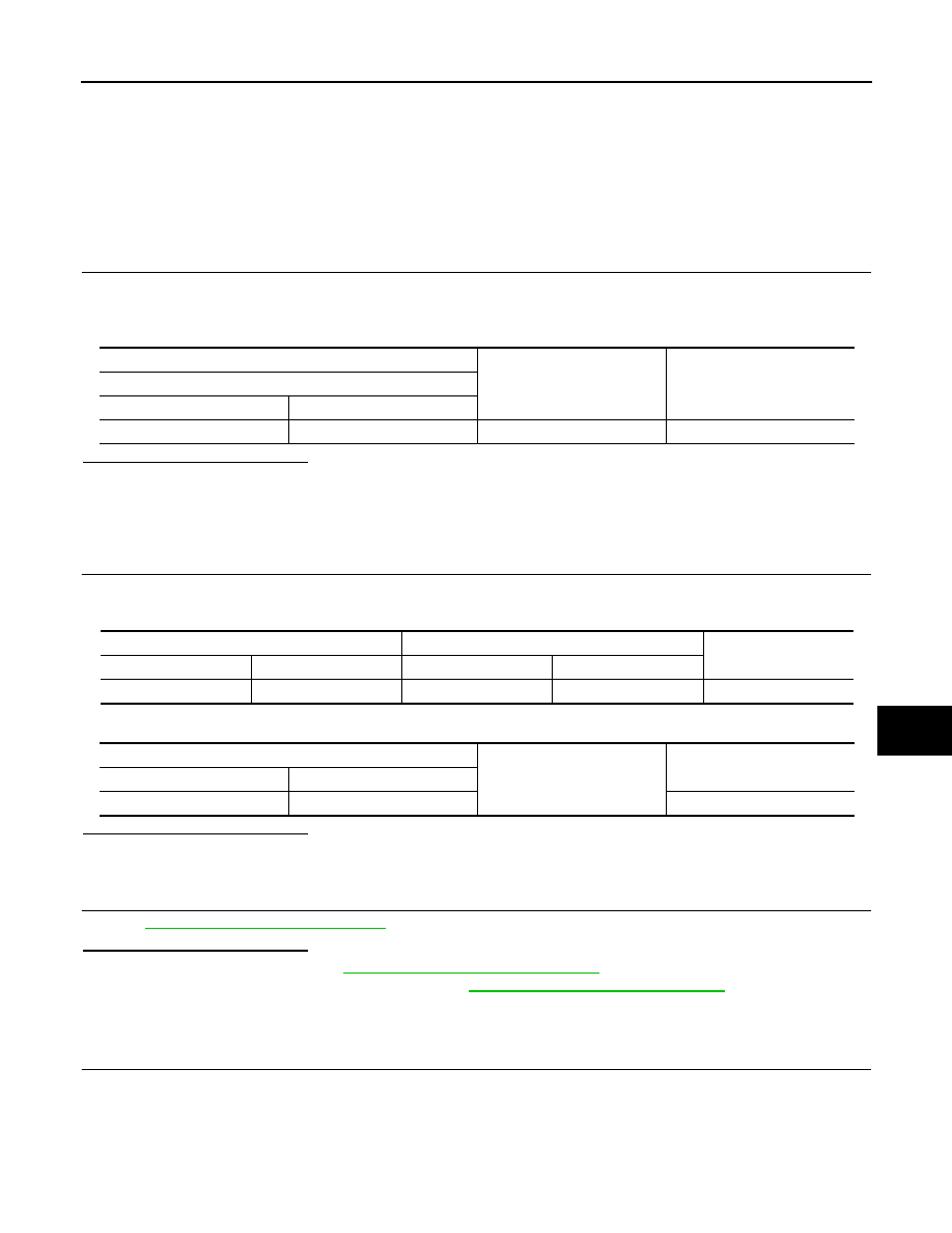
CHECK POWER SUPPLY CIRCUIT
1.
Turn the ignition switch OFF.
2.
Disconnect IPDM E/R connector.
3.
Check voltage between the IPDM E/R harness connector and the ground.
Is the measurement value normal?
YES
>> GO TO 3.
NO
>> Repair the harness or connector.
3.
CHECK GROUND CIRCUIT
Check continuity between the IPDM E/R harness connectors and the ground.
Does continuity exist?
YES
>> INSPECTION END
NO
>> Repair the harness or connector.
Signal name
Fuses and fusible link No.
Battery power supply
C
50
51
Terminals
Voltage
(Approx.)
(+)
(
−
)
IPDM E/R
Connector
Terminal
Ground
E4
1
Battery voltage
IPDM E/R
Ground
Continuity
Connector
Terminal
E5
12
Existed
E6
41
2014 GT-R

SEC-18
< DTC/CIRCUIT DIAGNOSIS >
[INTELLIGENT KEY SYSTEM]
HOOD SWITCH
HOOD SWITCH
Description
INFOID:0000000009163753
Hood switch is built into hood lock (RH) and connected to IPDM E/R which detects the open/close condition of
hood.
Diagnosis Procedure
INFOID:0000000009163755
1.
CHECK HOOD SWITCH CIRCUIT
1.
Turn ignition switch OFF.
2.
Disconnect IPDM E/R connector E9 and hood switch connector.
3.
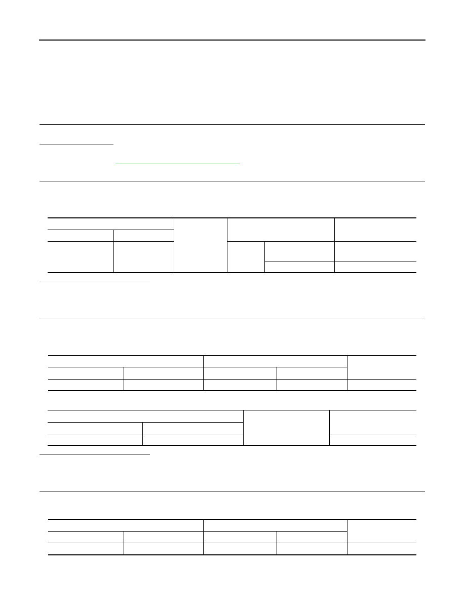
Check continuity between IPDM E/R harness connector and hood switch harness connector.
4.
Check continuity between IPDM E/R harness connector and ground.
Is the inspection result normal?
YES
>> GO TO 2.
NO
>> Repair or replace harness.
2.
CHECK IPDM E/R OUTPUT
1.
Connect IPDM E/R connector.
2.
Check voltage between IPDM E/R harness connector and ground.
Is the inspection result normal?
YES
>> GO TO 3.
NO
>> Replace IPDM E/R. Refer to
PCS-17, "Removal and Installation"
3.
CHECK HOOD SWITCH
SEC-18, "Component Inspection"
.
Is the inspection result normal?
YES
>> GO TO 4.
NO
>> Replace hood switch.
4.
CHECK INTERMITTENT INCIDENT
GI-38, "Intermittent Incident"
>> INSPECTION END
Component Inspection
INFOID:0000000009163756
1.
CHECK HOOD SWITCH
1.
Turn ignition switch OFF.
2.
Disconnect hood switch connector.
3.
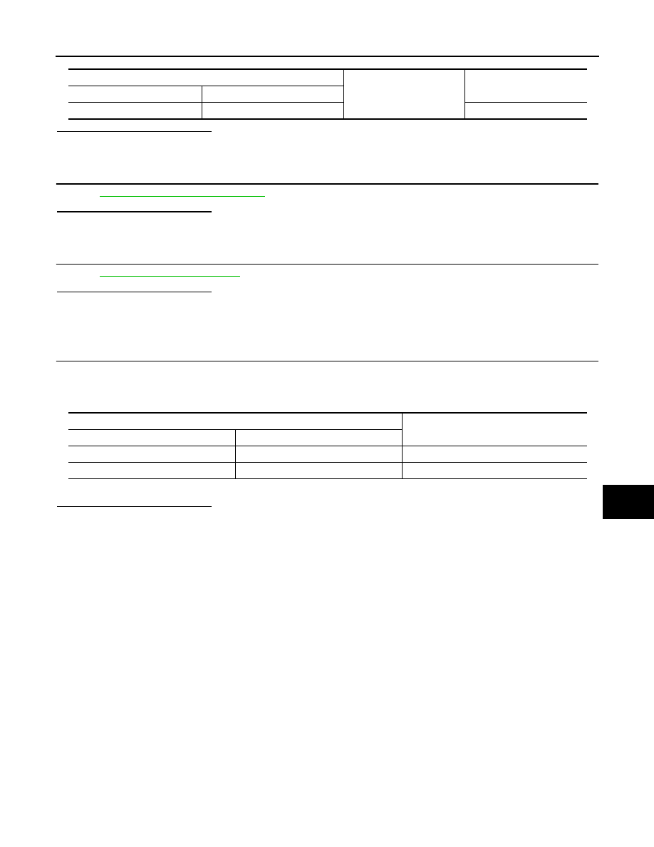
Check continuity between hood switch terminals.
IPDM E/R
Hood switch
Continuity
Connector
Terminal
Connector
Terminal
E9
104
E83
2
Existed
IPDM E/R
Ground
Continuity
Connector
Terminal
E9
104
Not existed
(+)
(–)
Voltage (V)
(Approx.)
IPDM E/R
Connector
Terminal
E9
104
Ground
Battery voltage
2014 GT-R

HOOD SWITCH
SEC-19
< DTC/CIRCUIT DIAGNOSIS >
[INTELLIGENT KEY SYSTEM]
C
D
E
F
G
H
I
J
L
M
A
B
SEC
N
O
P
Is the inspection result normal?
YES
>> INSPECTION END
NO
>> Replace hood switch. (Built is hood lock RH.)
Hood switch
Condition
Continuity
Terminal
1
2
Hood switch
Press
Not existed
Release
Existed
2014 GT-R
SEC-20
< DTC/CIRCUIT DIAGNOSIS >
[INTELLIGENT KEY SYSTEM]
HEADLAMP
HEADLAMP
Description
INFOID:0000000009205231
Headlamp lighting when vehicle security system is alarm phase.
Component Function Check
INFOID:0000000009205232
1.
CHECK HEADLAMP OPERATION
Check if headlamp operate by lighting switch.
Does headlamp come on when turning switch “ON”?
YES
>> Headlamp circuit is OK.
NO
>> Go to
.
Diagnosis Procedure
INFOID:0000000009205233
1.
CHECK HEADLAMP OPERATION
SEC-20, "Component Function Check"
Is the inspection result normal?
YES
>> GO TO 2.
NO
>> repair or replace the malfunctioning parts.
2.
CHECK INTERMITTENT INCIDENT
GI-38, "Intermittent Incident"
>> INSPECTION END
2014 GT-R
SECURITY INDICATOR LAMP
SEC-21
< DTC/CIRCUIT DIAGNOSIS >
[INTELLIGENT KEY SYSTEM]
C
D
E
F
G
H
I
J
L
M
A
B
SEC
N
O
P
SECURITY INDICATOR LAMP
Description
INFOID:0000000009163760
NVIS (Nissan Vehicle Immobilizer System-NATS) and vehicle security system conditions are indicated by blink
or illumination of security indicator lamp.
Diagnosis Procedure
INFOID:0000000009163762
1.
CHECK SECURITY INDICATOR LAMP POWER SUPPLY CIRCUIT
1.
Turn ignition switch OFF.
2.
Disconnect security indicator lamp connector.
3.
Check voltage between security indicator lamp harness connector and ground.
Is the inspection result normal?
YES
>> GO TO 2.
NO
>>
Check the following.
• 10 A fuse [No. 6, located in the fuse block (J/B)]
• Harness for open or short between security indicator lamp and fuse.
2.
CHECK SECURITY INDICATOR LAMP CIRCUIT
1.
Disconnect BCM connector.
2.
Check continuity between security indicator lamp harness connector and BCM harness connector.
3.
Check continuity between security indicator lamp harness connector and ground.
Is the inspection result normal?
YES
>> GO TO 3.
NO
>> Repair or replace harness.
3.
CHECK SECURITY INDICATOR LAMP
SEC-21, "Component Inspection"
.
Is the inspection result normal?
YES
>> Replace BCM. Refer to
BCS-20, "Removal and Installation"
NO
>> Replace security indicator lamp. Refer to
SEC-39, "Removal and Installation"
Component Inspection
INFOID:0000000009163763
1.
CHECK SECURITY INDICATOR LAMP
1.
Disconnect security indicator lamp connector.
2.
Check continuity between security indicator lamp terminals.
(+)
(–)
Voltage (V)
(Approx.)
Security indicator lamp
Connector
Terminal
M29
1
Ground
Battery voltage
Security indicator lamp
BCM
Continuity
Connector
Terminal
Connector
Terminal
M29
2
M123
141
Existed
Security indicator lamp
Ground
Continuity
Connector
Terminal
M29
2
Not existed
2014 GT-R

SEC-22
< DTC/CIRCUIT DIAGNOSIS >
[INTELLIGENT KEY SYSTEM]
SECURITY INDICATOR LAMP
Is the inspection result normal?
YES
>> INSPECTION END
NO
>> Replace security indicator lamp.
Terminal
Continuity
Security indicator lamp
(+)
(–)
1
2
Existed
2
1
Not existed
2014 GT-R
KEY WARNING LAMP
SEC-23
< DTC/CIRCUIT DIAGNOSIS >
[INTELLIGENT KEY SYSTEM]
C
D
E
F
G
H
I
J
L
M
A
B
SEC
N
O
P
KEY WARNING LAMP
Description
INFOID:0000000009163764
• Key warning lamp is located on combination meter.
• Performs operation method guide and warning together with buzzer.
Diagnosis Procedure
INFOID:0000000009163766
1.
CHECK KEY WARNING LAMP
DLK-81, "Component Function Check"
.
Is the inspection result normal?
Yes
>> GO TO 2.
No
>> Repair or replace key warning lamp circuit.
2.
CHECK INTERMITTENT INCIDENT
GI-38, "Intermittent Incident"
.
>> INSPECTION END
2014 GT-R
SEC-24
< DTC/CIRCUIT DIAGNOSIS >
[INTELLIGENT KEY SYSTEM]
HORN
HORN
Description
INFOID:0000000009163767
Perform answer-back for each operation with horn.
Diagnosis Procedure
INFOID:0000000009163769
1.
CHECK HORN FUNCTION
Check horn function with horn switch.
Do the horns sound?
YES
>> GO TO 2.
NO
>> Refer to
HRN-2, "Wiring Diagram - HORN -"
2.
CHECK HORN RELAY 1 POWER SUPPLY
1.
Turn ignition switch ON.
2.
Perform “ACTIVE TEST” (“HORN”) with CONSULT.
3.
Check voltage between horn relay 1 connector and ground.
Is the inspection result normal?
YES
>> GO TO 6.
NO
>> GO TO 3.
3.
CHECK HORN RELAY 1 CIRCUIT 1
1.
Turn ignition switch OFF.
2.
Disconnect horn relay 1 connector and diode connector.
3.
Check continuity between horn relay 1 harness connector and diode harness connector.
4.
Check continuity between horn relay 1 harness connector and ground.
Is the inspection result normal?
YES
>> GO TO 4.
NO
>> Repair or replace harness.
4.
CHECK HORN RELAY 1 CIRCUIT 2
1.
Disconnect IPDM E/R connector.
2.
Check continuity between IPDM E/R harness connector and diode connector.
3.
Check continuity between IPDM E/R harness connector and ground.
Horn relay 1
Ground
Test item
Voltage (V)
(Approx.)
Connector
Terminal
E11
1
HORN
ON
Battery voltage
→
0
→
Battery voltage
Other than above
Battery voltage
Horn relay 1
Diode
Continuity
Connector
Terminal
Connector
Terminal
E11
1
E107
3
Existed
Horn relay 1
Ground
Continuity
Connector
Terminal
E11
1
Not existed
IPDM E/R
Diode
Continuity
Connector
Terminal
Connector
Terminal
E6
44
E107
2
Existed
2014 GT-R
HORN
SEC-25
< DTC/CIRCUIT DIAGNOSIS >
[INTELLIGENT KEY SYSTEM]
C
D
E
F
G
H
I
J
L
M
A
B
SEC
N
O
P
Is the inspection result normal?
YES
>> GO TO 5.
NO
>> Repair or replace harness.
5.
CHECK DIODE
SEC-25, "Component Inspection"
.
Is the inspection result normal?
YES
>> GO TO 6.
NO
>> Replace diode.
6.
CHECK INTERMITTENT INCIDENT
GI-38, "Intermittent Incident"
.
Is the inspection result normal?
>> INSPECTION END
Component Inspection
INFOID:0000000009163770
1.
CHECK DIODE
1.
Turn ignition switch OFF.
2.
Disconnect diode.
3.
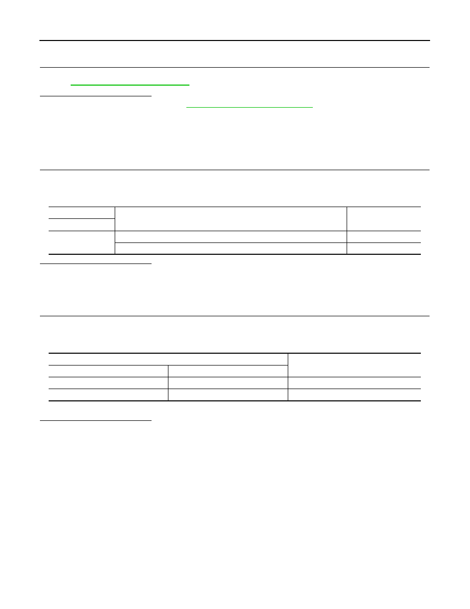
Check the continuity between diode terminals under the following conditions.
*: For a digital tester.
Is the inspection result normal?
YES
>> INSPECTION END
NO
>> Replace diode.
IPDM E/R
Ground
Continuity
Connector
Terminal
E6
44
Not existed
Terminal
Continuity
(+)*
(-)*
3
2
Existed
2
3
Not existed
2014 GT-R

SEC-26
< DTC/CIRCUIT DIAGNOSIS >
[INTELLIGENT KEY SYSTEM]
VEHICLE SECURITY HORN
VEHICLE SECURITY HORN
Description
INFOID:0000000009163771
Perform answer-back for each operation with horn.
Diagnosis Procedure
INFOID:0000000009163773
1.
CHECK FUSE
1.
Turn ignition switch OFF.
2.
Check that the following fuse are not fusing.
-
10A fuse [No.10 located in fuse block (J/B)]
Is the inspection result normal?
YES
>> GO TO 2.
NO
>> Replace the blown fuse after repairing the affected circuit if a fuse is blown.
2.
CHECK HORN RELAY 2 POWER SUPPLY
1.
Disconnect horn relay 2 connector.
2.
Check voltage between horn relay 2 connector and ground.
Is the inspection result normal?
YES
>> GO TO 3.
NO
>> Check horn relay 2 power supply circuit.
3.
CHECK VEHICLE SECURITY HORN POWER SUPPLY
1.
Connect horn relay 2 connector.
2.
Turn ignition switch ON.
3.
Perform “ACTIVE TEST” (“HORN”) with CONSULT.
4.
Check voltage between vehicle security horn connector and ground.
Is the inspection result normal?
YES
>> GO TO 4.
NO
>> GO TO 5.
4.
CHECK VEHICLE SECURITY HORN GROUND
1.
Turn ignition switch OFF.
2.
Disconnect vehicle security horn connector.
3.
Check continuity between vehicle security horn connector and ground.
Is the inspection result normal?
YES
>> Replace vehicle security horn.
NO
>> Repair or replace harness.
5.
CHECK HORN RELAY 2 CIRCUIT
Horn relay 2
Ground
Voltage (V)
(Approx.)
Connector
Terminal
E18
1
Battery voltage
Vehicle security horn
Ground
Test item
Voltage (V)
(Approx.)
Connector
Terminal
E32
1
HORN
ON
Battery voltage
→
0
→
Battery voltage
Other than above
Battery voltage
Vehicle security horn
Ground
Continuity
Connector
Terminal
E33
2
Existed
2014 GT-R

VEHICLE SECURITY HORN
SEC-27
< DTC/CIRCUIT DIAGNOSIS >
[INTELLIGENT KEY SYSTEM]
C
D
E
F
G
H
I
J
L
M
A
B
SEC
N
O
P
1.
Disconnect horn relay 2 connector.
2.
Check continuity between vehicle security horn harness connector and horn relay 2 connector.
3.
Check continuity between driver seat control unit harness connector and ground.
Is the inspection result normal?
YES
>> GO TO 6.
NO
>> Repair or replace harness.
6.
CHECK HORN RELAY 2
Check horn relay 2.
Refer to
SEC-28, "Component Inspection"
.
Is the inspection result normal?
YES
>> GO TO 7.
NO
>> Replace horn relay 2.
7.
CHECK HORN RELAY 2 CIRCUIT 1
1.
Disconnect diode connector.
2.
Check continuity between diode harness connector and horn relay 2 harness connector.
3.
Check continuity between diode harness connector and ground.
Is the inspection result normal?
YES
>> GO TO 8.
NO
>> Repair or replace harness.
8.
CHECK HORN RELAY 2 CIRCUIT 2
1.
Disconnect IPDM E/R connector.
2.
Check continuity between diode harness connector and IPDM E/R harness connector.
3.
Check continuity between diode harness connector and ground.
Is the inspection result normal?
YES
>> GO TO 9.
Vehicle security horn
Horn relay 2
Continuity
Connector
Terminal
Connector
Terminal
E32
1
E18
2
Existed
Vehicle security horn
Ground
Continuity
Connector
Terminal
E32
1
Not existed
Diode
Horn relay 2
Continuity
Connector
Terminal
Connector
Terminal
E107
1
E18
3
Existed
Diode
Ground
Continuity
Connector
Terminal
E107
1
Not existed
Diode
IPDM E/R
Continuity
Connector
Terminal
Connector
Terminal
E107
2
E6
44
Existed
Diode
Ground
Continuity
Connector
Terminal
E107
2
Not existed
2014 GT-R
SEC-28
< DTC/CIRCUIT DIAGNOSIS >
[INTELLIGENT KEY SYSTEM]
VEHICLE SECURITY HORN
NO
>> Repair or replace harness.
9.
CHECK DIODE
Check diode.
Refer to
SEC-28, "Component Inspection"
.
Is the inspection result normal?
YES
>> Replace IPDM E/R. Refer to
PCS-17, "Removal and Installation"
NO
>> Replace diode.
Component Inspection
INFOID:0000000009163774
HORN RELAY 2
1.
CHECK HORN RELAY 2
1.
Turn ignition switch OFF.
2.
Disconnect horn relay 2.
3.
Check horn relay 2.
Is the inspection result normal?
YES
>> INSPECTION END
NO
>> Replace horn relay 2.
DIODE
1.
CHECK DIODE
1.
Turn ignition switch OFF.
2.
Disconnect diode.
3.
Check the continuity between diode terminals under the following conditions.
*: For a digital tester.
Is the inspection result normal?
YES
>> INSPECTION END
NO
>> Replace diode.
Horn relay 2
Condition
Voltage
(Approx.)
Terminal
2
12 V direct current supply between terminals 1 and 3.
12 V
No current supply
0 V
Terminal
Continuity
(+)*
(-)*
1
2
Existed
2
1
Not existed
2014 GT-R

INTELLIGENT KEY SYSTEM/ENGINE START FUNCTION
SEC-29
< DTC/CIRCUIT DIAGNOSIS >
[INTELLIGENT KEY SYSTEM]
C
D
E
F
G
H
I
J
L
M
A
B
SEC
N
O
P
INTELLIGENT KEY SYSTEM/ENGINE START FUNCTION
Wiring Diagram - INTELLIGENT KEY SYSTEM/ENGINE START FUNCTION -
INFOID:0000000009163775
For connector terminal arrangements, harness layouts, and alphabets in a
(option abbreviation; if not
described in wiring diagram), refer to
GI-12, "Connector Information"
JCKWA1293GB
2014 GT-R

SEC-30
< DTC/CIRCUIT DIAGNOSIS >
[INTELLIGENT KEY SYSTEM]
INTELLIGENT KEY SYSTEM/ENGINE START FUNCTION
JCKWA1294GB
2014 GT-R

NISSAN VEHICLE IMMOBILIZER SYSTEM-NATS
SEC-31
< DTC/CIRCUIT DIAGNOSIS >
[INTELLIGENT KEY SYSTEM]
C
D
E
F
G
H
I
J
L
M
A
B
SEC
N
O
P
NISSAN VEHICLE IMMOBILIZER SYSTEM-NATS
Wiring Diagram - NVIS -
INFOID:0000000009163776
For connector terminal arrangements, harness layouts, and alphabets in a
(option abbreviation; if not
described in wiring diagram), refer to
GI-12, "Connector Information"
JCKWA1306GB
2014 GT-R

SEC-32
< DTC/CIRCUIT DIAGNOSIS >
[INTELLIGENT KEY SYSTEM]
NISSAN VEHICLE IMMOBILIZER SYSTEM-NATS
JCKWA1307GB
2014 GT-R
Нет комментариевНе стесняйтесь поделиться с нами вашим ценным мнением.
Текст