Almera Tino V10 (2003 year). Manual — part 178
SIIA1681E
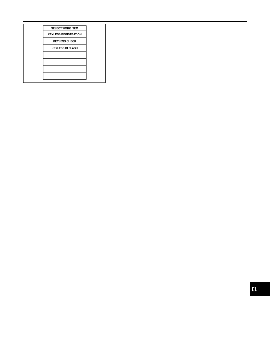
8.
The items are shown on the figure at left can be set up.
I
“KEYLESS CHECK”
Use this mode to confirm if a remote controller ID code is reg-
istered or not.
I
“KEYLESS REGISTRATION”
Use this mode to register a remote controller ID code.
NOTE:
Register the ID code when remote controller or smart entrance
control unit is replaced, or when additional remote controller
is required.
I
“KEYLESS DI FLASH”
This mode can be setting remote controller function.
GI
MA
EM
LC
EC
FE
CL
MT
AT
AX
SU
BR
ST
RS
BT
HA
SC
IDX
MULTI-REMOTE CONTROL SYSTEM
ID Code Entry Procedure (Cont’d)
EL-337
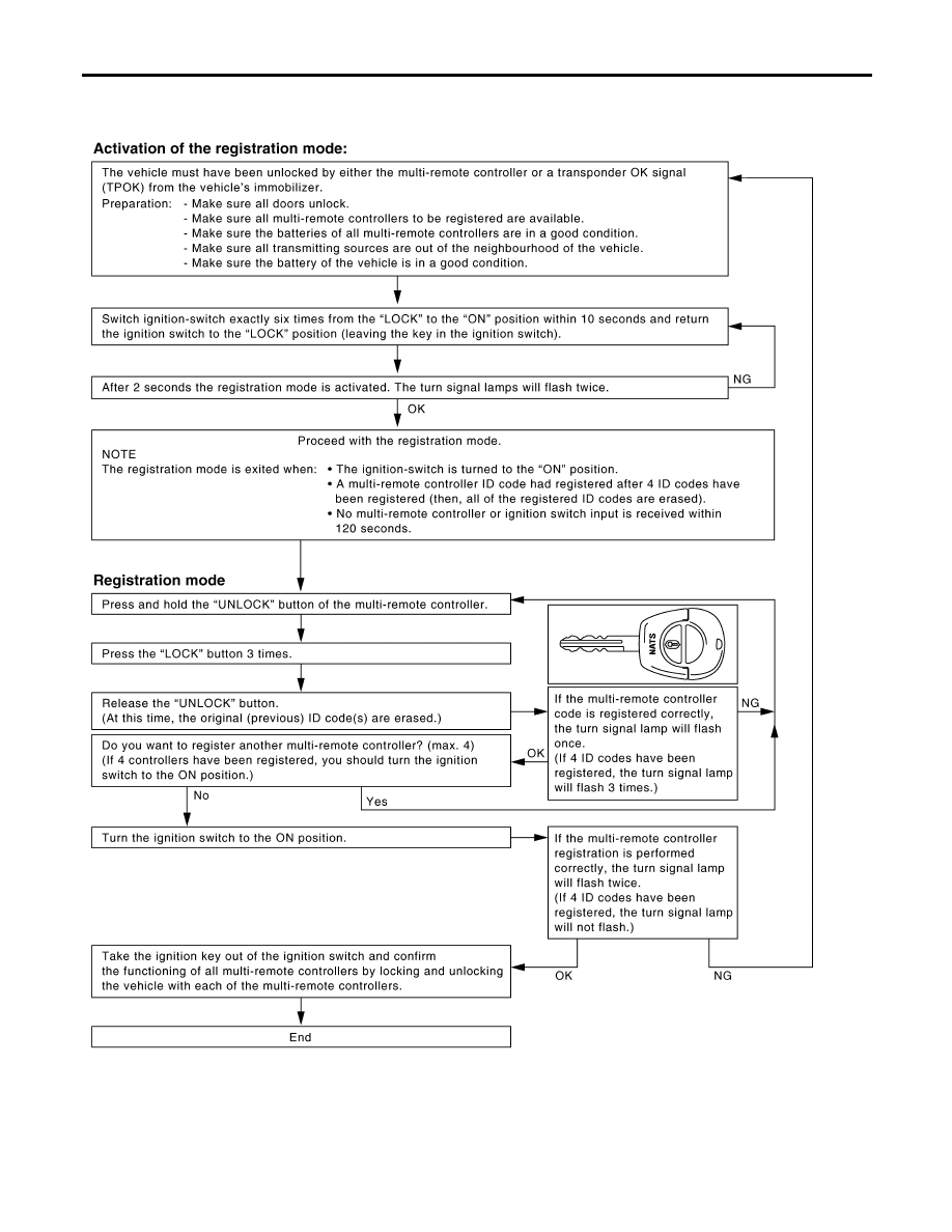
REMOTE CONTROLLER ID SET UP WITHOUT
CONSULT-II
NLEL0483S03
SEL497X
MULTI-REMOTE CONTROL SYSTEM
ID Code Entry Procedure (Cont’d)
EL-338

Remote Controller Battery Replacement
NLEL0484
SEL241X
GI
MA
EM
LC
EC
FE
CL
MT
AT
AX
SU
BR
ST
RS
BT
HA
SC
IDX
MULTI-REMOTE CONTROL SYSTEM
Remote Controller Battery Replacement
EL-339

Wiring Diagram — PRWIRE —
NLEL0576
YEL035E
THEFT WARNING SYSTEM
Wiring Diagram — PRWIRE —
EL-340

Description
NLEL0577
OUTLINE
NLEL0577S01
The smart entrance control unit totally controls the following body electrical system operations.
I
Warning chime, refer to EL-125, “WARNING CHIME”.
I
Rear defogger and door mirror defogger, refer to EL-177, “REAR WINDOW DEFOGGER”.
I
Power door lock, refer to EL-264, “POWER DOOR LOCK SYSTEM”.
I
Power door lock - Super lock - (RHD models), refer to EL-290, “POWER DOOR LOCK — SUPER LOCK
—”.
I
Multi-remote control system, refer to EL-322, “MULTI-REMOTE CONTROL SYSTEM”.
I
NATS (Nissan Anti-Theft system), refer to EL-352, “NATS (NISSAN ANTI-THEFT SYSTEM)”.
I
Interior lamp, refer to EL-77, “INTERIOR ROOM LAMP”.
Also, smart entrance control unit has the “sleep/wake-up control” function. Smart entrance control unit puts
itself (the whole smart entrance control unit) to sleep under certain conditions to prevent unnecessary power
consumption. Then, when a certain input is detected, the system wakes itself up. For more detailed
information, refer to EL-341, “SLEEP/WAKE-UP CONTROL”.
INTERIOR LAMP/SPOT LAMP/VANITY MIRROR ILLUMINATION
NLEL0577S02
The lamps turn off automatically when the interior lamp, spot lamp or/and vanity mirror illumination are illumi-
nated with the ignition key in the OFF position, if the lamp remains lit by the door switch open signal or if the
lamp switch is in the ON position for more than 30 minutes.
After lamps are turned off by the smart entrance control unit, the lamps illuminate again when:
I
Driver’s door is locked or unlocked with remote controller, door lock/unlock switch or door key cylinder.
I
Ignition switch is turned to ON.
I
Door is opened or closed,
I
Key is inserted into ignition key cylinder.
REAR WINDOW DEFOGGER/DOOR MIRROR DEFOGGER
NLEL0577S03
Rear window defogger is turned off in approximately 15 minutes after the rear window defogger switch is turned
on.
SLEEP/WAKE-UP CONTROL
NLEL0577S04
Sleep Control
NLEL0577S0401
“Sleep” control prevents unnecessary power consumption. After the following conditions are met, the smart
entrance control unit suspends the operation. The whole smart entrance control unit is set in the “sleep” mode.
I
Ignition switch “OFF”
I
All electrical loads (in the smart entrance control unit) “OFF”
I
Timer “OFF”
I
Each switch do not input
Wake-up Control
NLEL0577S0402
When the smart entrance control unit detects a “wake-up” signal, it wakes up the whole system and starts
operating again. When any one of the following switches are turned ON, the “sleep” mode is canceled:
I
Ignition switch
I
Hazard switch
I
Headlamp switch
I
Hood switch
I
Luggage room lamp switch
I
Each door switch
GI
MA
EM
LC
EC
FE
CL
MT
AT
AX
SU
BR
ST
RS
BT
HA
SC
IDX
SMART ENTRANCE CONTROL SYSTEM
Description
EL-341

INPUT/OUTPUT
=NLEL0577S05
System
Input
Output
Power door lock
Door lock/unlock switch
Key switch (Insert)
Door switches
Door lock actuators
Back door release actuator
Multi-remote control
Key switch (Insert) (For RHD models)
Ignition switch (ON)
Door switches
Multi-remote controller signal
Door lock/unlock switch
Hazard warning lamp
Door lock actuator
Interior room lamp
Warning chime
Key switch (Insert) (For RHD models)
Ignition switch (ON)
Lighting switch (1st)
Door switch driver side
Warning chime (located in smart entrance
control unit)
Rear window defogger and door mirror
defogger
Ignition switch (ON)
Rear window defogger switch
Rear window defogger relay
Interior room lamp
Door switches
Multi-remote controller signal (lock/unlock)
Door lock/unlock switches (lock/unlock)
Luggage room lamp switch (sedan mod-
els)
Ignition switch (ON)
Key switch (Insert)
Interior room lamp
Luggage room lamp
Step lamp
Spot lamp
Vanity mirror
SMART ENTRANCE CONTROL SYSTEM
Description (Cont’d)
EL-342

CONSULT-II
=NLEL0578
DIAGNOSTIC ITEMS APPLICATION
NLEL0578S01
Item (CONSULT-II screen
terms)
Diagnosed system
DATA MONITOR
WORK SUPPORT
DOOR LOCKING
Power door lock (For LHD
models)
Super lock (For RHD models)
X
X
RR DEFOG
Rear window defogger
X
KEY REMINDER
Warning chime (For LHD mod-
els)
X
LIGHT ON REMINDER
Warning chime
X
ROOM LAMP
Interior room lamps
X
THEFT WARNING
Theft warning system
X
X
KEYLESS ENTRY
Multi-remote control system
X
X
DIRECTION INDICATORS
Direction indicator sound
X
X
SEC-E C/U
SEC self-diagnosis
X
X: Applicable
For diagnostic item in each control system, refer to the relevant pages for each system.
The description of DATA MONITOR and WORK SUPORT, refer to EL-343, “DATA MONITOR MODE or EL-344, WORK SUPPORT
MODE”.
DATA MONITOR MODE
NLEL0578S02
Item (CONSULT-II screen terms)
Diagnosed system
IGNITION SW
Indicates [ON/OFF] condition of ignition switch.
KEY IN DETECT
Indicates [ON/OFF] condition of electronic key switch.
DOOR SW DR RR
Indicates [ON/OFF] condition of rear door switch (driver side).
DOOR SW AS RR
Indicates [ON/OFF] condition of rear door switch (passenger side).
AS DOOR SW
Indicates [ON/OFF] condition of front door switch (passenger side).
DR DOOR SW
Indicates [ON/OFF] condition of front door switch (driver side).
CDL LOCK SW
Indicates [ON/OFF] condition of door lock/unlock switch (lock signal).
CDL UNLOCK SW
Indicates [ON/OFF] condition of door lock/unlock switch (unlock signal).
TRUNK OPEN SW
Indicates [ON/OFF] condition of
HOOD OPEN SW
Indicates [ON/OFF] condition of hood switch.
HAZARD SW
Indicates [ON/OFF] condition of hazard switch.
RH TURN SW
Indicates [ON/OFF] condition of turn signal switch.
LH TURN SW
Indicates [ON/OFF] condition of turn signal switch.
REAR DEF SW
Indicates [ON/OFF] condition of multifunction switch (defogger switch).
RKE LOCK
Indicates [ON/OFF] condition of lock signal from remote controller.
RKE UNLOCK
Indicates [ON/OFF] condition of unlock signal from remote controller.
RKE SEL UNLOCK
Indicates [ON/OFF] condition of select unlock signal from remote controller.
RKE TRUNK REL
Indicates [ON/OFF] condition of trunk open signal from remote controller.
BATTERY CHECK
Indicates [ON/OFF] condition of remote controller battery.
TAIL LAMP ON
Indicates [ON/OFF] condition of lighting switch.
GI
MA
EM
LC
EC
FE
CL
MT
AT
AX
SU
BR
ST
RS
BT
HA
SC
IDX
SMART ENTRANCE CONTROL SYSTEM
CONSULT-II
EL-343

Item (CONSULT-II screen terms)
Diagnosed system
KEY CYL LK
Indicates [ON/OFF] condition of lock signal from door key cylinder.
KEY CYL UNLK
Indicates [ON/OFF] condition of unlock signal from door key cylinder.
MODE
Indicates [CMFRT/SCRTY] condition of multi-remote control system.
CAN COMM
Indicates the communication condition of CAN communication line.
CAN CIRC 1
CAN CIRC 2
CAN CIRC 3
WORK SUPPORT MODE
NLEL0578S03
Mode
Description
Test item
DOOR LOCKING
AUTO RE-LOCK
This mode can set auto re-lock function.
SELECTIVE UNLOCK
This mode can set select unlock function.
KEYLESS ENTRY
KEYLESS REGISTRATION
This mode can register remote controller ID.
KEYLESS CHECK
This mode can check whether water remote controller
ID code is registered or not.
KEYLESS DI FLASH
This mode can set remote controller function.
DIRECTION INDICATORS
AUDIBLE TRAILER WARNING
This mode can set audible trailer warning function.
SELF-DIAG RESULTS MODE
NLEL0578S04
Diagnosis item
Description
Repair order
RH FLASHER (S) BULB BROKEN
RH turn signal lamp system is mal-
functioning.
Check turn signal lamp system. Refer to EL-77,
“TURN SIGNAL AND HAZARD WARNING LAMPS”.
LH FLASHER (S) BULB BROKEN
LH turn signal lamp system is mal-
functioning.
Check turn signal lamp system. Refer to EL-125,
“TURN SIGNAL AND HAZARD WARNING LAMPS”.
RH FLASHER CIRCUIT OVER
CURRENT
RH turn signal lamp circuit is open or
shorted.
Check turn signal lamp system. Refer to EL-125,
“TURN SIGNAL AND HAZARD WARNING LAMPS”.
LH FLASHER CIRCUIT OVER
CURRENT
LH turn signal lamp circuit is open or
shorted.
Check turn signal lamp system. Refer to EL-125,
“TURN SIGNAL AND HAZARD WARNING LAMPS”.
CAN COMM CIRCUIT*
CAN communication line is open or
shorted.
Check CAN communication line. Refer to EL-351,
“CAN Communication Line Check”.
*: If this malfunction is displayed, first perform the trouble diagnosis.
SMART ENTRANCE CONTROL SYSTEM
CONSULT-II (Cont’d)
EL-344

MBIB0906E
CONSULT-II INSPECTION PROCEDURE
=NLEL0578S05
1.
Turn ignition switch “OFF”.
2.
Connect “CONSULT-II” to the data link connector.
MBIB0233E
3.
Turn ignition switch “ON”.
4.
Touch “START”.
SIIA1678E
5.
Touch “SMART ENTRANCE”.
YEL324E
6.
Touch “SEC-E C/U”.
YEL575E
7.
Select self-diag mode.
“SELF-DIAG RESULTS” and “DATA MONITOR” are available.
GI
MA
EM
LC
EC
FE
CL
MT
AT
AX
SU
BR
ST
RS
BT
HA
SC
IDX
SMART ENTRANCE CONTROL SYSTEM
CONSULT-II (Cont’d)
EL-345

Schematic
NLEL0579
YEL018E
SMART ENTRANCE CONTROL SYSTEM
Schematic
EL-346

YEL019E
GI
MA
EM
LC
EC
FE
CL
MT
AT
AX
SU
BR
ST
RS
BT
HA
SC
IDX
SMART ENTRANCE CONTROL SYSTEM
Schematic (Cont’d)
EL-347

Smart Entrance Control Unit Inspection Table
NLEL0580
Terminal
No.
Wire
color
Connections
Operated condition
Voltage (Approximate values)
1
G
NATS antenna amp.
(Power supply)
—
Approx. 5V
2
G/OR
NATS antenna amp.
(Ground)
—
—
3
G/W
NATS antenna amp.
(Signal line)
Moment when key was inserted.
The needle of analog tester
swings immediately after insert-
ing key.
4
G/Y
NATS antenna amp.
(Signal line)
Moment when key was inserted
The needle of analog tester
swings immediately after insert-
ing key.
5
B/R
Key switch
Ignition key Removed
,
Inserted
0V
,
12V
8
L
CAN communication line
—
—
9
Y
Audio unit
Ignition key removed or inserted
MKIB0191E
11
R
CAN communication line
—
—
13
GY
Door lock/unlock switches
Neutral
,
Locks
12V
,
0V
14
L
Door lock/unlock switches
Neutral
,
Unlocks
12V
,
0V
15
LG
Hood switch
Hood switch:
ON (Open)
,
OFF (Closed)
0V
,
12V
17
R/G
Tail lamp switch
Lighting switch: OFF
,
1st or 2nd
0V
,
12V
18
LG
CONSULT-II
—
—
22
L/Y
Multifunction switch
(Rear window defogger switch)
[Ignition switch “ON”]
Multifunction switch: Press
,
Release (Only when pressed)
7V
,
0V
25
G/OR
Combination switch
(Turn signal switch)
Turn signal switch:
Neutral
,
Left turn position
12V
,
0V
26
L/B
Combination switch
(Turn signal switch)
Turn signal switch:
Neutral
,
Right turn position
12V
,
0V
27
Y/B
Vehicle security horn relay
(RHD models)
When theft warning system:
Armed
,
Disarmed
0V
,
12V
28
R/Y
Interior room lamp
When interior lamp is operated using
remote controller (Lamp switch in
“DOOR” position)
12V
,
0V
29
Y/G
Ignition key switch
Ignition key is in “ON” position
12V
30
G/R
Hazard switch
Hazard switch: OFF
,
ON
12V
,
0V
31
W
Rear window defogger relay
[Ignition switch “ON”]
Rear window defogger switch:
OFF
,
ON
12V
,
0V
SMART ENTRANCE CONTROL SYSTEM
Smart Entrance Control Unit Inspection Table
EL-348

Terminal
No.
Wire
color
Connections
Operated condition
Voltage (Approximate values)
32
LG/B
Cooling fan relay
[Ignition switch“ ON”]
Cooling fan: Operating
,
Not operat-
ing
0V
,
12V
33
LG/R
Cooling fan relay
[Ignition switch “ON”]
Cooling fan: Operating
,
Not operat-
ing
0V
,
12V
34
L/Y
Security indicator
Ignition switch ON
,
OFF
12V
,
0V
41
L
Air conditioner relay
[Engine is running]
Air conditioner switch: ON
,
OFF
12V
,
0V
43
R/W
Front door switch
(Driver side)
Front door (Driver side):
Open
,
Closed
12V
,
0V
44
L/OR
Front door switch
(Passenger side)
Front door (Passenger side):
Open
,
Closed
0V
,
12V
49
W/L
Power source
—
12V
51
L/R
Driver door lock actuator
Door lock & unlock switch:
Free
,
Lock
0V
,
12V
52
Y
Door lock actuators
Door lock & unlock switch:
Free
,
Unlock
0V
,
12V
53
B
Ground
—
0V
54
G/Y
Door lock actuators
Door lock & unlock switch:
Free
,
Unlock
0V
,
12V
55
W/B
Power door super lock actuator
(Front)
Remote controller door lock switch:
Free
,
Unlock
0V
,
12V
56
R/B
Power source
—
12V
58
*1
Starter motor (M/T or A/T mod-
els)
Ignition switch: OFF
,
START posi-
tion
0V
,
12V
59
*2
Starter motor (M/T or A/T mod-
els)
Ignition switch: OFF
,
START posi-
tion
0V
,
12V
62
L/R
Headlamp washer motor
[Headlamp switch 1st or 2nd position]
Washer switch: OFF
,
ON
12V
,
0V
63
G/Y
RH turn signal lamp
[When door lock or unlock is oper-
ated using remote controller]
Turn signal lamp: OFF
,
ON
,
OFF
0V
,
12V
,
0V
64
G/B
LH turn signal lamp
[When door lock or unlock is oper-
ated using remote controller]
Turn signal lamp: OFF
,
ON
,
OFF
0V
,
12V
,
0V
*1: B/Y (M/T models), G/OR (A/T models)
*2: B/W (M/T models), P (A/T models)
GI
MA
EM
LC
EC
FE
CL
MT
AT
AX
SU
BR
ST
RS
BT
HA
SC
IDX
SMART ENTRANCE CONTROL SYSTEM
Smart Entrance Control Unit Inspection Table (Cont’d)
EL-349

Trouble Diagnoses
=NLEL0581
PRELIMINARY CHECK
NLEL0581S01
1
CHECK “SELF-DIAG RESULTS” MODE WITH CONSULT-II
Check smart entrance system trouble diagnosis (SELF-DIAG RESULTS) in “SEC-E CE” mode with CONSULT-II. Refer to
EL-344, “SELF-DIAG RESULTS MODE”.
Can “SELF-DIAG RESULTS” mode be displayed?
Yes
©
GO TO 2.
No
©
GO TO 3.
2
CHECK DISPLAY ITEM
Check display item in “SELF-DIAG RESULTS” mode.
Is any malfunction indicated in “SELF-DIAG RESULTS” mode?
Yes
©
GO TO EL-344, “SELF-DIAG RESULTS MODE”.
No
©
Inspection end.
3
CHECK POWER SUPPLY AND GROUND CIRCUIT
Refer to EL-330, “Power Supply and Ground Circuit Check”.
OK or NG
OK
©
Replace smart entrance control unit.
NG
©
Repair or replace harness.
SMART ENTRANCE CONTROL SYSTEM
Trouble Diagnoses
EL-350

CAN Communication Line Check
=NLEL0583
1
CHECK CAN COMMUNICATION CIRCUIT
1. Turn ignition switch “ON”.
2. Select “SELF-DIAG RESULTS” in “SEC-E CE” mode with CONSULT-II.
3. The “CAN COMM CIRCUIT” is detected.
Yes or No
Yes
©
Print out CONSULT-II screen, GO TO 2.
No
©
INSPECTION END
2
CHECK CAN COMMUNICATION SIGNALS
1. Turn ignition switch “ON”.
2. Select “CAN DIAG SUPPORT MNTR” in ”SEC-E CE” mode with CONSULT-II.
3. Print out the CONSULT-II screen.
SEC898C
©
GO TO EL-459, “CAN COMMUNICATION”.
GI
MA
EM
LC
EC
FE
CL
MT
AT
AX
SU
BR
ST
RS
BT
HA
SC
IDX
SMART ENTRANCE CONTROL SYSTEM
CAN Communication Line Check
EL-351

Component Parts and Harness Connetor
Location
For details, refer to “ELECTRICAL UNIT LOCATION” (EL-600) and
“HARNESS LAYOUT” (EL-596).
System Description
NLEL0585
NATS (Nissan Anti-Theft System) has the following immobilizer functions:
I
Since only NATS ignition keys, whose ID nos. have been registered into the ECM and IMMU of NATS,
allow the engine to run, operation of a stolen vehicle without a NATS registered key is prevented by NATS.
That is to say, NATS will immobilize the engine if someone tries to start it without the registered key of
NATS.
I
This version of NATS has dongle unit to improve its anti-theft performance (RHD models for Europe).
Dongle unit has its own ID which is registered into NATS IMMU. So if dongle unit is replaced, initialization
must be carried out.
I
When malfunction of dongle unit is detected:
The security indicator lamp illuminates for about 15 minutes after ignition switch is turned to ON.
−
When dongle unit has a malfunction and the indicator lamp is illuminated, engine can not be started.
However engine can be started only one time when security indicator lamp turns off in about 15 minutes
after ignition switch is turned to ON.
I
All of the originally supplied ignition key IDs have been NATS registered.
If requested by the vehicle owner, a maximum of five key IDs can be registered into the NATS compo-
nents.
I
The security indicator blinks when the ignition switch is in “OFF” or “ACC” position. Therefore, NATS warns
outsiders that the vehicle is equipped with the anti-theft system.
I
When NATS detects trouble, the security indicator lamp lights up as follows.
Condition IGN ON and
With dongle
Without dongle
MIL
Security indicator
MIL
Security indicator
NATS malfunction
(except dongle unit) is
detected
—
1. 6 times blinking
2. Staying ON after igni-
tion switch is turned
ON
—
Staying ON
Only malfunction of
dongle unit is detected.
—
Staying ON for about 15
minutes after ignition
switch is turned ON
—
—
Malfunction of NATS
and engine related parts
are detected.
Staying ON
1. 6 times blinking
2. Staying ON after igni-
tion switch is turned
ON
Staying ON
Staying ON
Only engine related part
malfunction is detected.
Staying ON
—
Staying ON
—
Just after initialization of
NATS
—
6 times blinking
—
—
I
NATS trouble diagnoses, system initialization and additional registration of other NATS ignition key IDs
must be carried out using CONSULT-II hardware and CONSULT-II NATS software.
Regarding the procedures of NATS initialization and NATS ignition key ID registration, refer to CONSULT-II
operation manual, NATS.
I
When servicing a malfunction of the NATS (indicated by lighting up of Security Indicator Lamp) or
NATS (NISSAN ANTI-THEFT SYSTEM)
Component Parts and Harness Connetor Location
EL-352
Нет комментариевНе стесняйтесь поделиться с нами вашим ценным мнением.
Текст