Qashqai J11. Transaxle & Transmission — part 39

TM-610
< SYMPTOM DIAGNOSIS >
[CVT: RE0F10G]
CVT CONTROL SYSTEM
Symptom Table 2
Other
No creep at all.
2
4
3
7
8
9
10
11
12
5
6
13
14
1
Vehicle cannot run in any position.
8
2
5
6
7
9
10
11
3
4
12
13
1
With selector lever in D position, driv-
ing is not possible.
8
2
5
6
7
9
10
11
3
4
12
13
1
With selector lever in R position, driv-
ing is not possible.
8
2
5
6
7
9
10
11
3
4
12
13
1
Judder occurs during lock-up.
2
6
3
4
5
7
8
1
Strange noise in D position.
2
3
4
1
Strange noise in R position.
2
3
4
1
Strange noise in N position.
2
3
4
1
Vehicle does not decelerate by engine
brake.
7
3
4
5
6
2
8
1
Maximum speed low.
2
3
5
6
7
8
9
11
4
10
1
With selector lever in P position, vehi-
cle does not enter parking condition or,
with selector lever in another position,
parking condition is not cancelled.
1
2
Vehicle runs with CVT in P position.
1
3
4
2
Vehicle runs with CVT in N position.
1
3
4
2
Engine stall.
2
6
3
4
8
9
5
7
10
1
Engine stalls when selector lever shift-
ed N
→
D or R.
2
6
3
4
5
7
1
Engine speed does not return to idle.
2
4
3
5
1
Engine does not start in N or P posi-
tion.
3
2
1
Engine starts in positions other than N
or P.
3
2
1
Symptom
En
gin
e
sy
st
em
CAN c
o
m
m
u
n
ic
a
tio
n
lin
e
T
ra
n
s
m
is
s
ion
ra
ng
e s
w
itc
h
(P07
05
, P0
70
6)
In
pu
t s
p
e
e
d
se
ns
or
(P07
17
)
Pri
m
ary
sp
ee
d se
ns
or (P07
15
)
Out
p
u
t
s
p
e
ed se
ns
or (P27
65
)
CVT flu
id tem
p
e
rat
ure
se
ns
or (P07
12
,
P0
71
3)
Prim
a
ry
p
res
su
re se
ns
or (P08
4C,
P
0
8
4
D)
Sec
o
n
d
a
ry p
res
sure
se
ns
or (P08
41
,
P0
84
7,
P08
4
8
)
T
o
rq
ue
co
nv
ert
e
r c
lu
tch
s
o
le
n
o
id
v
a
lv
e
(P07
40
, P0
74
3,
P07
4
4
)
St
a
ll t
e
s
t
CVT po
sit
ion
Power suppl
y
Control valve
CVT
f
lui
d
l
e
vel
an
d
s
ta
te
Ig
ni
tio
n
switch
an
d st
a
rter
EC9-137
TM-485
TM-5
08
TM-6
19
TM-6
02
TM-6
29
TM-6
15
PG
-5
6
,
STR-18

CVT CONTROL SYSTEM
TM-611
< SYMPTOM DIAGNOSIS >
[CVT: RE0F10G]
C
E
F
G
H
I
J
K
L
M
A
B
TM
N
O
P
Symptom
T
o
rqu
e
c
o
nv
erte
r
T
ran
sm
is
si
on
ran
g
e
s
w
itc
h
Oil p
u
m
p
Forwa
rd cl
utc
h
Rev
e
rs
e brak
e
Pl
an
et
a
ry ge
ar
Bearings
Park
in
g m
e
ch
an
ism
St
o
p
l
a
m
p
s
w
it
c
h
S
h
if
t lo
ck
s
o
le
n
o
id
CVT sh
if
t se
le
ctor
Shift Shock
Large shock (N
→
D position)
2
1
Large shock (N
→
R position)
2
1
Shock is too large for lock-up.
1
Slips/Will
Not Engage
Vehicle cannot be started from D
position.
3
1
2
Vehicle cannot be started from R
position.
4
1
2
3
Does not lock-up.
1
3
2
Does not hold lock-up condition.
1
3
2
Lock-up is not released.
1
2
With selector lever in D position,
acceleration is extremely poor.
1
3
2
With selector lever in R position,
acceleration is extremely poor.
1
4
2
3
Slips at lock-up.
1
2

TM-612
< SYMPTOM DIAGNOSIS >
[CVT: RE0F10G]
CVT CONTROL SYSTEM
Other
No creep at all.
1
6
2
4
5
3
Vehicle cannot run in all posi-
tions.
1
2
4
5
3
6
With selector lever in D position,
driving is not possible.
1
2
4
3
5
With selector lever in R position,
driving is not possible.
1
2
4
3
5
Judder occurs during lock-up.
1
Strange noise in D position.
1
2
4
3
5
Strange noise in R position.
1
2
4
3
Strange noise in N position.
1
2
3
Maximum speed low.
1
5
2
4
3
With selector lever in P position,
vehicle does not enter parking
condition or, with selector lever in
another position, parking condi-
tion is not cancelled.
1
Vehicle runs with CVT in P posi-
tion.
2
1
Vehicle runs with CVT in N posi-
tion.
2
3
1
Engine stall.
1
Engine stalls when selector lever
shifted N
→
D or R.
1
When brake pedal is depressed
with ignition switch ON, selector
lever cannot be shifted from P po-
sition to other position.
1
2
3
When brake pedal is not de-
pressed with ignition switch ON,
selector lever can be shifted from
P position to other position.
1
2
3
Symptom
T
o
rq
ue
co
nv
ert
e
r
T
ran
sm
is
si
on
ran
g
e
swi
tch
Oil pum
p
Fo
rward
c
lut
ch
Re
vers
e b
rak
e
Pl
an
et
a
ry ge
ar
Beari
n
gs
Parki
n
g mechanism
S
top
la
mp
s
w
itc
h
Sh
if
t lo
ck
s
o
le
no
id
CVT sh
if
t
se
le
cto
r
TM
-6
5
6
TM-653
TM
-6
0
6
TM
-6
0
5
TM
-6
1
7

CVT FLUID
TM-613
< PERIODIC MAINTENANCE >
[CVT: RE0F10G]
C
E
F
G
H
I
J
K
L
M
A
B
TM
N
O
P
PERIODIC MAINTENANCE
CVT FLUID
Inspection
INFOID:0000000010245671
FLUID LEAKAGE
• Check transaxle surrounding area (oil seal and plug etc.)for fluid
leakage.
• If anything is found, repair or replace damaged parts and adjust
CVT fluid level. Refer to
Replacement
INFOID:0000000010245672
CAUTION:
• Always use shop paper. Never use shop cloth.
• Replace a drain plug gasket with new ones at the final stage of the operation when installing.
• Use caution when looking into the drain hole as there is a risk of dripping fluid entering the eye.
• After replacement, always perform CVT fluid leakage check.
1.
Select “Data Monitor” in “TRANSMISSION” using CONSULT.
2.
Select “FLUID TEMP” and confirm that the CVT fluid temperature is 40
°
C (104
°
F) or less.
3.
Check that the selector lever is in the “P” position, then completely engage the parking brake.
4.
Lift up the vehicle.
5.
Remove the drain plug and drain the CVT fluid from the oil pan. Refer to
6.
Install the drain plug to oil pan.
CAUTION:
Drain plug gasket use the old one.
7.
Remove the overflow plug
from converter housing.
SMA146B
Recommended fluid and fluid capacity
: Refer to
MA-59, "Fluids and Lubricants"
: Vehicle front
JSDIA3714ZZ

TM-614
< PERIODIC MAINTENANCE >
[CVT: RE0F10G]
CVT FLUID
8.
Install the charging pipe set (KV311039S0) (A) into the overflow
plug hole.
CAUTION:
Tighten the charging pipe by hand.
9.
Install the ATF changer hose (B) to the charging pipe.
CAUTION:
Press the ATF changer hose all the way onto the charging
pipe until it stops.
10. Fill approximately 3 liter (2-5/8 lmp qt) of the CVT fluid.
11. Remove the ATF changer hose and charging pipe, then install
the overflow plug.
NOTE:
Perform this work quickly because CVT fluid leaks.
12. Lift down the vehicle.
13. Start the engine.
14. While depressing the brake pedal, shift the selector lever to the entire position from “P” to “D”, and shift it
to the “P” position.
NOTE:
Hold the lever at each position for 5 seconds.
15. Check that the CONSULT “Data Monitor” in “FLUID TEMP” is 35
°
C (95
°
F) to 45
°
C (113
°
F).
16. Stop the engine.
17. Lift up the vehicle.
18. Remove the drain plug, and then drain CVT fluid from oil pan.
19. Repeat steps 6 to 18 (one time).
20. Tighten the drain plug to the specified torque. Refer to
21. Remove the overflow plug.
22. Install the charging pipe set (KV311039S0) into the overflow plug hole.
CAUTION:
Tighten the charging pipe by hand.
23. Install the ATF changer hose to the charging pipe.
CAUTION:
Press the ATF changer hose all the way onto the charging pipe until it stops.
24. Fill approximately 3 liter (2-5/8 lmp qt) of the CVT fluid.
25. Remove the ATF changer hose and charging pipe, then install the overflow plug.
NOTE:
Perform this work quickly because CVT fluid leaks.
26. Lift down the vehicle.
27. Start the engine.
28. While depressing the brake pedal, shift the selector lever to the entire position from “P” to “D”, and shift it
to the “P” position.
NOTE:
Hold the lever at each position for 5 seconds.
29. Check that the CONSULT “Data Monitor” in “FLUID TEMP” is 35
°
C (95
°
F) to 45
°
C (113
°
F).
30. Lift up the vehicle.
31. Remove the overflow plug and confirm that the CVT fluid is drained from the overflow plug hole.
CAUTION:
Perform this work with the vehicle idling.
NOTE:
If the CVT fluid is not drained, refer to “Adjustment” and refill with the CVT fluid.
32. When the flow of CVT fluid slows to a drip, tighten the overflow plug to the specified torque. Refer to
CAUTION:
Never reuse O-ring.
33. Lift down the vehicle.
JSDIA3713ZZ

CVT FLUID
TM-615
< PERIODIC MAINTENANCE >
[CVT: RE0F10G]
C
E
F
G
H
I
J
K
L
M
A
B
TM
N
O
P
34. Select “Data Monitor” in “TRANSMISSION” using CONSULT.
35. Select “CONFORM CVTF DETERIORTN”.
36. Select “Erase”.
37. Perform air bleeding of electric oil pump. Refer to
38. Stop the engine.
Adjustment
INFOID:0000000010245673
CAUTION:
• During adjustment of the CVT fluid level, check CONSULT so that the oil temperature may be main-
tained from 35 to 45
°
C (95 to 113
°
F).
• During adjustment of the CVT fluid level, check that the engine speed is maintaining 500 rpm.
• Use caution when looking into the drain hole as there is a risk of dripping fluid entering the eye.
1.
Check that the selector lever is in the “P” position, then completely engage the parking brake.
2.
Start the engine.
3.
Adjust the CVT fluid temperature to be approximately 40
°
C (104
°
F).
NOTE:
The CVT fluid is largely affected by temperature. Therefore be sure to use CONSULT and check the
“FLUID TEMP” under “TRANSMISSION” in “Data Monitor” while adjusting.
4.
While depressing the brake pedal, shift the selector lever to the entire position from “P” to “D”, and shift it
to the “P” position.
NOTE:
Hold the lever at each position for 5 seconds.
5.
Lift up the vehicle.
6.
Check that there is no CVT fluid leakage.
7.
Remove the overflow plug
from converter housing.
8.
Install the charging pipe set (KV311039S0) (A) into the overflow
plug hole.
CAUTION:
Tighten the charging pipe by hand.
9.
Install the ATF changer hose (B) to the charging pipe.
CAUTION:
Press the ATF changer hose all the way onto the charging
pipe until it stops.
10. Fill approximately 0.5 liter (1/2 lmp qt) of the CVT fluid.
11. Remove the ATF changer hose from the charging pipe, and
check that the CVT fluid drains out from the charging pipe. If it
does not drain out, perform charging again.
CAUTION:
Perform this work with the vehicle idling.
12. When the flow of CVT fluid slows to a drip, remove the charging pipe from the converter housing.
13. Tighten the overflow plug to the specified torque. Refer to
.
CAUTION:
Never reuse O-ring.
Recommended fluid and fluid capacity
: Refer to
MA-59, "Fluids and Lubricants"
: Vehicle front
JSDIA3714ZZ
JSDIA3713ZZ
TM-616
< PERIODIC MAINTENANCE >
[CVT: RE0F10G]
CVT FLUID
14. Lift down the vehicle.
15. Stop the engine.
CVT SHIFT SELECTOR
TM-617
< REMOVAL AND INSTALLATION >
[CVT: RE0F10G]
C
E
F
G
H
I
J
K
L
M
A
B
TM
N
O
P
REMOVAL AND INSTALLATION
CVT SHIFT SELECTOR
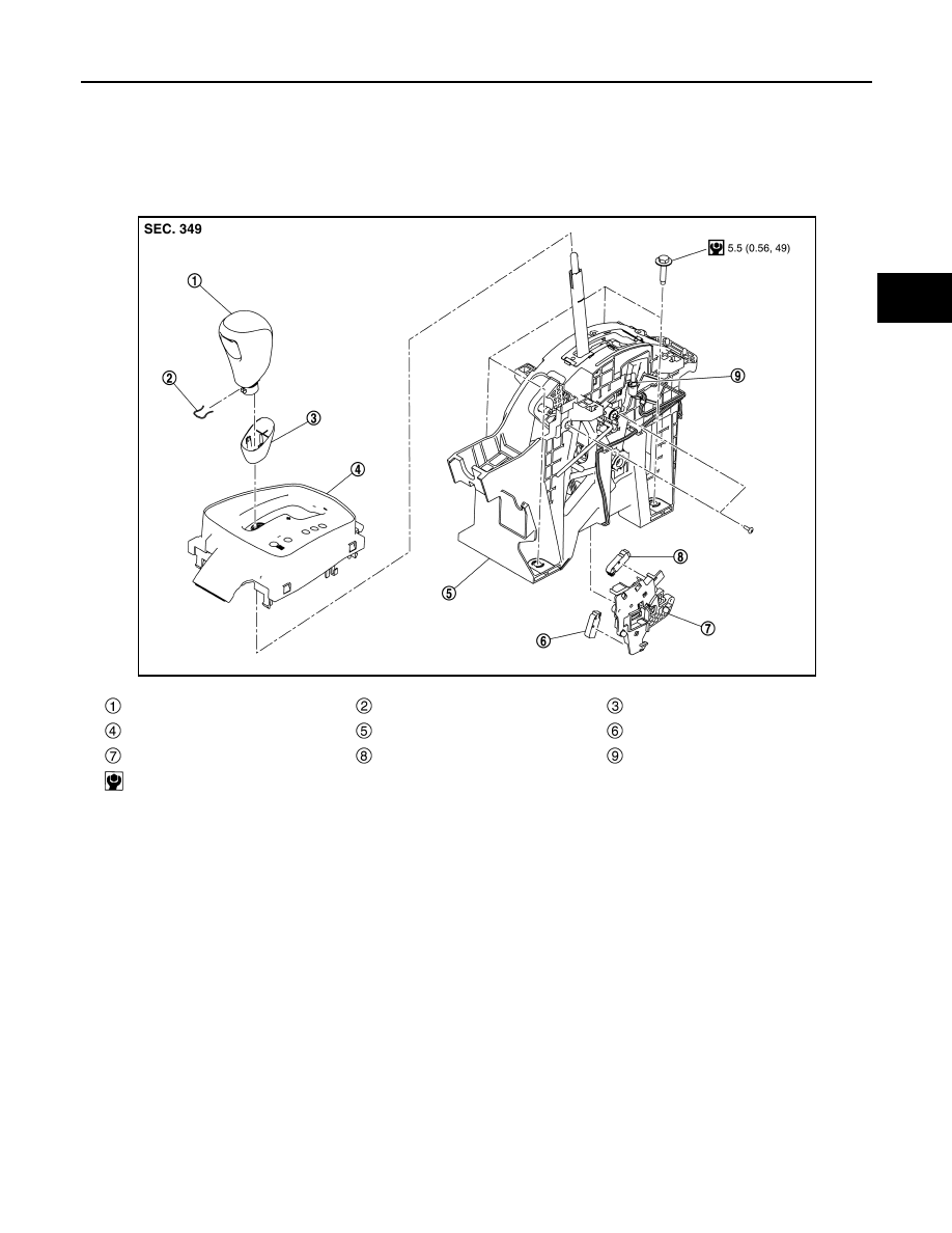
Exploded View
INFOID:0000000010245674
Removal and Installation
INFOID:0000000010245675
CAUTION:
Always apply the parking brake before removal and installation.
REMOVAL
1.
Apply the parking brake.
CAUTION:
Make sure the vehicle cannot move with the parking brake applied.
2.
Turn ignition switch ON.
3.
Shift the selector lever to “N” position.
4.
Turn ignition switch OFF.
5.
Remove the shift selector knob with the following procedure.
Selector lever knob
Lock pin
Selector lever knob cover
Position indication panel
CVT shift selector assembly
Park position switch
Shift lock unit
Detent switch*
Position indicator bulb
: N·m (kg-m, in-lb)
*: With push engine starter
JSDIA5217GB

TM-618
< REMOVAL AND INSTALLATION >
[CVT: RE0F10G]
CVT SHIFT SELECTOR
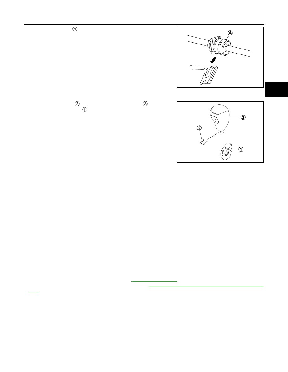
a.
Slide the selector lever knob cover
down.
CAUTION:
Never damage the knob cover.
b.
Pull out the lock pin
from the selector lever knob
.
c.
Pull the selector lever knob and the selector lever knob cover
upwards to remove them.
6.
Remove the center console. Refer to
.
7.
Shift the selector lever to “P” position.
8.
Disconnect the tip
of control cable and remove socket
from
the CVT shift selector assembly.
9.
Disconnect the CVT shift selector connector
.
10. Remove the CVT shift selector assembly from the vehicle.
INSTALLATION
Note the followings and install in the reverse order of removal.
• Pay attention to the following when connecting the control cable to the CVT shift selector assembly.
1.
When connecting the control cable
to the CVT shift selector
assembly
, face the grooved surface of the rib
up and insert
the control cable until it stops.
NOTE:
Apply multi-purpose grease to control cable eye before installa-
tion.
JSDIA2778ZZ
JSDIA4220ZZ
JSDIA5384ZZ
JSDIA1624ZZ
CVT SHIFT SELECTOR
TM-619
< REMOVAL AND INSTALLATION >
[CVT: RE0F10G]
C
E
F
G
H
I
J
K
L
M
A
B
TM
N
O
P
2.
Install the socket
onto the CVT shift selector assembly.
CAUTION:
• Place the socket onto the CVT shift selector assembly,
then fasten it in place from above.
• Check that the pulling on the socket does not disconnect
it.
• Follow the procedure below and place the selector lever knob onto the CVT shift selector.
1.
Install the lock pin
onto the selector lever knob
.
2.
Install the knob cover
onto the selector lever knob.
3.
Shift the selector lever to “N” position.
4.
Press the selector lever knob onto the selector lever until it
clicks.
CAUTION:
• When install, never press selector button.
• Never strike the selector lever knob to press it into place.
5.
After installing selector lever knob, pull the knob to check that it
does not become disconnected.
Disassembly and Assembly
INFOID:0000000010476164
DISASSEMBLY
1.
Remove the position lamp.
2.
Disengage the hooks (4 locations), and lift up the position indication panel to separate it from the CVT shift
selector assembly.
CAUTION:
Never damage the CVT shift selector assembly.
3.
Remove shift lock unit mounting screws.
4.
Remove the shift lock unit from the CVT shift selector assembly.
5.
Disconnect the park position switch connector, detent switch connector and shift lock solenoid connector
from the shift lock unit.
ASSEMBLY
Assemble in the reverse order of disassembly.
Inspection
INFOID:0000000010245676
INSPECTION AFTER INSTALLATION
• Check the CVT shift selector position. Refer to
• Check that shift lock can be forcible release. Refer to
TM-445, "SHIFT LOCK SYSTEM : System Descrip-
• The key can be removed only when the selector lever is in the “P” position. (Without push engine starter)
• It must not be possible to turn the ignition switch to LOCK when the selector lever is not in the “P” position.
(Without push engine starter)
JSDIA1810ZZ
JSDIA2778ZZ

TM-620
< REMOVAL AND INSTALLATION >
[CVT: RE0F10G]
CONTROL CABLE
CONTROL CABLE
Exploded View
INFOID:0000000010245677
Removal and Installation
INFOID:0000000010245678
CAUTION:
Always apply the parking brake before performing removal and installation.
REMOVAL
1.
Apply the parking brake.
CAUTION:
Make sure the vehicle cannot move with the parking brake applied.
2.
Remove the center console. Refer to
IP-19, "Removal and Installation"
.
3.
Remove the position lamp.
Control cable
Lock plate
Transaxle assembly
Bracket
Bracket
CVT shift selector assembly
Manual lever
Grommet
: N·m (kg-m, ft-lb)
: N·m (kg-m, in-lb)
JSDIA5218GB

CONTROL CABLE
TM-621
< REMOVAL AND INSTALLATION >
[CVT: RE0F10G]
C
E
F
G
H
I
J
K
L
M
A
B
TM
N
O
P
4.
Disengage the hooks
(4 locations), and lift up the position
indication panel
to separate it from the CVT shift selector.
CAUTION:
Never damage the CVT shift selector assembly.
5.
Disconnect the tip
of control cable and remove socket
from
the CVT shift selector assembly.
6.
Remove the air duct (inlet) and air cleaner case. Refer to
7.
Remove the battery. Refer to
PG-155, "Removal and Installa-
8.
Remove the TCM bracket and TCM. Refer to
9.
Remove the battery mounting bracket assembly. Refer to
10. Remove the control cable nut (
) and remove the control cable
from the manual lever
.
11. Remove the lock plate
and remove the control cable
from
bracket .
12. Remove the exhaust front tube. Refer to
13. Remove heat plate.
14. Remove the control cable
from bracket
.
15. Remove the control cable from the vehicle.
JSDIA4229ZZ
JSDIA4220ZZ
: Vehicle front
JSDIA4147ZZ
: Vehicle front
JSDIA4148ZZ
: Vehicle front
JPDIA0107ZZ

TM-622
< REMOVAL AND INSTALLATION >
[CVT: RE0F10G]
CONTROL CABLE
INSTALLATION
Note the following and install in the reverse order of removal.
• Pay attention to the following when connecting the control cable to the CVT shift selector assembly.
1.
When connecting the control cable
to the CVT shift selector
assembly
, face the grooved surface of the rib
up and insert
the control cable until it stops.
NOTE:
Apply multi-purpose grease to control cable eye before installa-
tion.
2.
Install the socket
onto the CVT shift selector assembly.
CAUTION:
• Place the socket onto the CVT shift selector assembly,
then fasten it in place from above.
• Check that the pulling on the socket does not disconnect
it.
Inspection and Adjustment
INFOID:0000000010245679
ADJUSTMENT AFTER INSTALLATION
Adjust the CVT position. Refer to
INSPECTION AFTER ADJUSTMENT
Check the CVT shift selector position after the adjustment. Refer to
JSDIA1624ZZ
JSDIA1810ZZ

KEY INTERLOCK CABLE
TM-623
< REMOVAL AND INSTALLATION >
[CVT: RE0F10G]
C
E
F
G
H
I
J
K
L
M
A
B
TM
N
O
P
KEY INTERLOCK CABLE
Exploded View
INFOID:0000000010249391
Removal and Installation
INFOID:0000000010249392
REMOVAL
CAUTION:
Always apply the parking brake before performing removal and installation.
1.
Remove the lower instrument panel (driver side) and steering column cover. Refer to
.
2.
Remove the center console. Refer to
IP-19, "Removal and Installation"
.
3.
Press the pawls
of the key interlock cable slider
while slid-
ing it in the direction of the casing cap
, and separate the
adjusting holder
and slider.
4.
Remove the key interlock cable from the shift selector.
5.
Lift the clip
in the direction of the arrow (
) and remove in
the direction of the arrow (
).
6.
Remove the key interlock cable from the key cylinder.
7.
Disengage the clip and disconnect the key interlock cable from
the vehicle.
Shift selector assembly
Clip
Key interlock cable
Clip
Key cylinder
JSDIA5227ZZ
:Key interlock rod
JSDIA1797ZZ
: Key interlock cable
: Key cylinder
JSDIA1798ZZ

TM-624
< REMOVAL AND INSTALLATION >
[CVT: RE0F10G]
KEY INTERLOCK CABLE
INSTALLATION
1.
Move the shift selector to "P" position.
2.
Turn the ignition switch to ACC or ON position.
3.
Install the holder of key interlock cable to key cylinder.
4.
Install the clip
in the direction of the arrow (
) and push it
in the direction of the arrow (
).
5.
Turn the ignition switch to LOCK position.
6.
Install the adjusting holder
onto the key interlock rod
, then
install the casing cap
onto the shift selector cable bracket
.
CAUTION:
• When installing the key interlock cable, do not bend or
twist the cable forcefully.
• After connecting the key interlock cable to the shift selec-
tor cable bracket, be sure to check that the casing cap is
completely fastened to the cable bracket. If the casing cap
is easily displaced, replace the key interlock cable.
7.
Slide the key interlock cable slider
toward the key interlock
rod
side and install the adjusting holder
and key interlock
rod.
CAUTION:
• Never squeeze the pawls on the key interlock cable slider
when holding the slider.
• Never apply force in a perpendicular direction to the key
interlock rod when sliding the slider.
8.
Install the center console. Refer to
9.
Install the lower instrument panel (driver side) and steering col-
umn cover. Refer to
IP-13, "Removal and Installation"
.
Inspection
INFOID:0000000010249393
INSPECTION AFTER INSTALLATION
• Check the CVT position. If a malfunction is found, adjust the CVT position. Refer to
.
• The key can be removed only when the selector lever is in the “P” position.
• It must not be possible to turn the ignition switch to LOCK when the selector lever is not in the “P” position.
: Key interlock cable
: Key cylinder
JSDIA3589ZZ
JSDIA1799ZZ
JSDIA2644ZZ

TCM
TM-625
< REMOVAL AND INSTALLATION >
[CVT: RE0F10G]
C
E
F
G
H
I
J
K
L
M
A
B
TM
N
O
P
TCM
Exploded View
INFOID:0000000010245682
Removal and Installation
INFOID:0000000010245683
CAUTION:
• Never impact the TCM when removing or installing TCM.
• Before replacing TCM and transaxle assembly simultaneously, perform “ADDITIONAL SERVICE
WHEN REPLACING TCM AND TRANSAXLE ASSEMBLY”. Refer to
• Before replacing TCM, perform “ADDITIONAL SERVICE WHEN REPLACING TCM”. Refer to
REMOVAL
1.
Remove the battery. Refer to
PG-155, "Removal and Installation"
2.
Remove the air duct (inlet). Refer to
.
3.
Disconnect the TCM harness connector
and ECM harness
connector .
Bracket
TCM
: N·m (kg-m, in-lb)
JSDIA5219GB
JSDIA5385ZZ
Нет комментариевНе стесняйтесь поделиться с нами вашим ценным мнением.
Текст