Qashqai J11. Steering control system — part 2
EPS CONTROL UNIT
STC-17
< ECU DIAGNOSIS INFORMATION >
C
D
E
F
H
I
J
K
L
M
A
B
STC
N
O
P
*1: Almost in accordance with the value of “MOTOR SIG”. It is not a malfunction though these values are not
accorded when steering quickly.
*2: Normally displays 100%. In case of an excessive stationary steering, the assist curvature gradually falls.
However, it returns to 100% when left standing.
*3: It is not a malfunction, though it might not be corresponding just after ignition switch in turned ON.
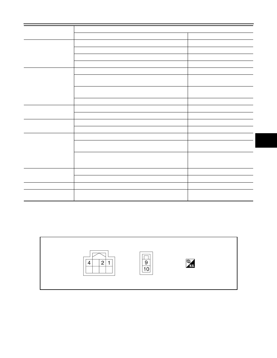
TERMINAL LAYOUT
PHYSICAL VALUES
STOP/START STATUS
When stop/start system is inactive
INACT
When stop/start system is restarting
AUTO ST
When stop/start system is active
ACT
When stop/start system is interrupted
CANCEL
IPA ON
When EPS system operation conditions are not satisfied
Off1
When there is a malfunction in EPS system or Intelligent Parking
Assist
Off2
When assist torque is larger than command value from Intelligent
Parking Assist
Off3
Normal
On
IPA STATUS 1
When Intelligent Parking Assist is active
On
When Intelligent Parking Assist is inactive
Off
STOP/START SYSTEM
When stop/start system is active
On
When stop/start system is prohibited
Off
IPA STATUS 2
When Intelligent Parking Assist is inactive
Off
When Intelligent Parking System is active (steering wheel is not
turned)
On1
The following cases
• When Intelligent Parking Assist is active
• When steering wheel is turned
On2
IPA STATUS 3
When Intelligent Parking Assist is normal
NORMAL
When Intelligent Parking Assist malfunction occurs
MALF
IPA TARGET CURRENT
When Intelligent Parking Assist is active
0 – 70 (A)
EPS CONTROL CUR-
RENT
When EPS system is active
0 – 90 (A)
Monitor item
Data monitor
Condition
Display value
JSGIA1434ZZ

STC-18
< ECU DIAGNOSIS INFORMATION >
EPS CONTROL UNIT
Fail-safe
INFOID:0000000010452107
• If any malfunction occurs in the system and control unit detects the malfunction, power steering warning
lamp on combination meter turns ON to indicate system malfunction.
• When power steering warning lamp is ON, the system enters into a manual steering state. (Control turning
force steering wheel becomes heavy.)
Protection Function
INFOID:0000000010452108
EPS control unit decreases the output signal to EPS motor while extremely using the power steering function
(e.g., full steering) consecutively for protecting EPS motor and EPS control unit (Overload protection control).
While activating overload protection control, the assist torque gradually decreases, and the steering wheel
turning force becomes heavy. The normal assist torque reactivates by no steering.
DTC Inspection Priority Chart
INFOID:0000000010452109
When multiple DTCs are detected simultaneously, check one by one depending on the following priority list.
Terminal No.
(Wire Color)
Description
Condition
Value
(Approx.)
+
−
Signal name
Input/Output
1
(P)
—
CAN-L
Input/Output
—
—
2
(L)
—
CAN-H
Input/Output
—
—
4
(SB)
Ground
Ignition power supply
Input
Ignition switch: ON
10.5 V – 16 V
Ignition switch: OFF
0 V
9
(R)
Ground
Battery power supply
Input
Always
10.5 V – 16 V
10
(B)
Ground
Ground
—
Always
0 V
DTC
Fail-safe condition
C1601
The assist force is reduced according to the voltage, eventually ending with manual steering state
C1604
Manual steering state
C1606
C1607
C1608
C1609
Non-speed sensitive steering assist
U1000
• Non-speed sensitive steering assist
• Intelligent Parking Assist function (controlled from around view monitor) or Stop/Start system function (controlled
from ECM) is stopped
U1010
Normal control
U1970
Intelligent Parking Assist function (controlled from around view monitor) is stopped
Priority
Priority order item (DTC)
1
• U1000 CAN COMM CIRCUIT
• U1010 CONTROL UNIT(CAN)
2
• U1970 AVM
• C1609 CAN VHCL SPEED
3
C1601 BATTERY BOLT
4
• C1604 TORQUE SENSOR
• C1606 EPS MOTOR
• C1607 EPS EEPROM
• C1608 CONTROL UNIT

EPS CONTROL UNIT
STC-19
< ECU DIAGNOSIS INFORMATION >
C
D
E
F
H
I
J
K
L
M
A
B
STC
N
O
P
DTC Index
INFOID:0000000010452110
*: Even if DTC is detected, power steering warning lamp does not turns ON when assist torque is generated.
NOTE:
If two or more DTCs are detected, refer to
STC-18, "DTC Inspection Priority Chart"
.
DTC
Items (CONSULT screen terms)
Power steering
warning lamp
Reference
C1601
BATTERY VOLT
ON
C1604
TORQUE SENSOR
ON
C1606
EPS MOTOR
ON
C1607
EEPROM
OFF
C1608
CONTROL UNIT
ON/OFF*
C1609
CAN VHCL SPEED
OFF
U1000
CAN COMM CIRCUIT
OFF
U1010
CONTROL UNIT(CAN)
OFF
U1970
AVM
OFF
STC-20
< WIRING DIAGRAM >
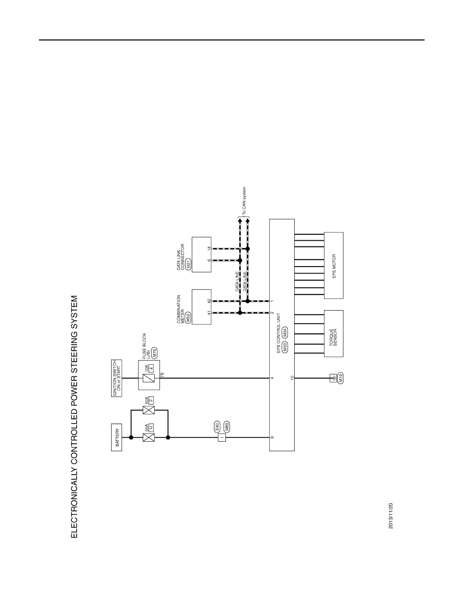
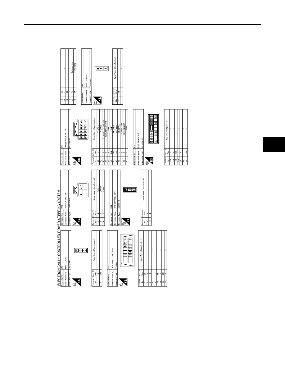
EPS SYSTEM
WIRING DIAGRAM
EPS SYSTEM
Wiring Diagram
INFOID:0000000010452111
JRGWC0950GB
EPS SYSTEM
STC-21
< WIRING DIAGRAM >
C
D
E
F
H
I
J
K
L
M
A
B
STC
N
O
P
JRGWC1878GB
STC-22
< BASIC INSPECTION >
DIAGNOSIS AND REPAIR WORK FLOW
BASIC INSPECTION
DIAGNOSIS AND REPAIR WORK FLOW
Work Flow
INFOID:0000000010452112
DETAILED FLOW
1.
INTERVIEW FROM THE CUSTOMER
Clarify customer complaints before inspection. First of all, perform an interview utilizing
and reproduce symptoms as well as fully understand it. Ask customer about his/her complaints
carefully. Check symptoms by driving vehicle with customer, if necessary.
NOTE:
Customers are not professional. Never guess easily like “maybe the customer means that...,” or “maybe the
customer mentions this symptom”.
>> GO TO 2.
2.
CHECK SYMPTOM
Reproduce the symptom that is indicated by the customer, based on the information from the customer
obtained by interview. Also check that the symptom is not caused by protection function. Refer to
NOTE:
When the symptom is caused by normal operation, fully inspect each portion and obtain the understanding of
customer that the symptom is not caused by a malfunction.
>> GO TO 3.
3.
PERFORM SELF-DIAGNOSIS
With CONSULT
Perform self-diagnosis.
Is any DTC detected?
YES
>> Record or print DTC freeze frame data (FFD). GO TO 4.
NO
>> GO TO 6.
4.
RECHECK SYMPTOM
With CONSULT
1.
Erase self-diagnostic results.
2.
Perform DTC confirmation procedures for the error detected system.
NOTE:
If some DTCs are detected at the same time, determine the order for performing the diagnosis based on
18, "DTC Inspection Priority Chart"
Is any DTC detected?
YES
>> GO TO 5.
NO
>> Check harness and connectors based on the information obtained by interview. Refer to
.
5.
REPAIR OR REPLACE ERROR-DETECTED PARTS
• Repair or replace error-detected parts.
• Reconnect part or connector after repairing or replacing.
• When DTC is detected, erase self-diagnostic results for “EPS”.
>> GO TO 7.
6.
IDENTIFY ERROR-DETECTED SYSTEM BY SYMPTOM DIAGNOSIS
Estimate error-detected system based on symptom diagnosis and perform inspection.
Can the error-detected system be identified?

DIAGNOSIS AND REPAIR WORK FLOW
STC-23
< BASIC INSPECTION >
C
D
E
F
H
I
J
K
L
M
A
B
STC
N
O
P
YES
>> GO TO 7.
NO
>> Check harness and connectors based on the information obtained by interview. Refer to
.
7.
FINAL CHECK
With CONSULT
1.
Check the reference value for EPS control unit.
2.
Recheck the symptom and check that symptom is not reproduced on the same conditions.
Is the symptom reproduced?
YES
>> GO TO 3.
NO
>> INSPECTION END
Diagnostic Work Sheet
INFOID:0000000010452113
Description
• In general, customers have their own criteria for a problem. Therefore, it is important to understand the
symptom and status well enough by asking the customer about his/her concerns carefully. To systemize all
the information for the diagnosis, prepare the interview sheet referring to the interview points.
• In some cases, multiple conditions that appear simultaneously may cause a DTC to be detected.
Interview sheet sample
Interview sheet
Customer
name
MR/MS
Registration
number
Initial year
registration
Vehicle type
VIN
Storage date
Engine
Mileage
km (Mile)
Symptom
The steering wheel position (center) is in the wrong position.
Power steering warning lamp turns on.
Noise
Vibration
Others
(
)
First occurrence
Recently
Others (
)
Frequency of occurrence
Always
Under a certain conditions of
Sometimes (time(s)/day)
Climate con-
ditions
Irrelevant
Weather
Fine
Cloud
Rain
Snow
Others (
)
Temperature
Hot
Warm
Cool
Cold
Temperature [Approx.
°
C (
°
F)]
Relative humidity
High
Moderate
Low
Road conditions
Urban area
Suburb area
High way
Mounting road (uphill or down hill)
Rough road
Operation conditions, etc.
Irrelevant
When engine starts
During idling
During driving
During acceleration
At constant speed driving
During deceleration
During cornering (right curve or left curve)
During steering

STC-24
< BASIC INSPECTION >
DIAGNOSIS AND REPAIR WORK FLOW
Other conditions
Memo
Interview sheet
Customer
name
MR/MS
Registration
number
Initial year
registration
Vehicle type
VIN
Storage date
Engine
Mileage
km (Mile)

C1601 BATTERY POWER SUPPLY
STC-25
< DTC/CIRCUIT DIAGNOSIS >
C
D
E
F
H
I
J
K
L
M
A
B
STC
N
O
P
DTC/CIRCUIT DIAGNOSIS
C1601 BATTERY POWER SUPPLY
DTC Logic
INFOID:0000000010452114
DTC DETECTION LOGIC
DTC CONFIRMATION PROCEDURE
1.
PRECONDITIONING
If “DTC CONFIRMATION PROCEDURE” has been previously conducted, always turn ignition switch OFF and
wait at least 10 seconds before conducting the next test.
>> GO TO 2.
2.
DTC REPRODUCTION PROCEDURE
With CONSULT
1.
Turn the ignition switch OFF to ON.
2.
Perform “EPS/DAST 3” self-diagnosis.
Is DTC “C1601” detected?
YES
>> Proceed to diagnosis procedure. Refer to
NO
>> INSPECTION END
Diagnosis Procedure
INFOID:0000000010452115
1.
CHECK EPS CONTROL UNIT GROUND CIRCUIT
1.
Turn ignition switch OFF.
2.
Disconnect EPS control unit harness connector.
3.
Check continuity between EPS control unit harness connector terminal and ground.
Is the inspection result normal?
YES
>> GO TO 2.
NO
>> Repair open circuit or short to ground or short to power in harness or connectors.
2.
CHECK EPS CONTROL UNIT POWER SUPPLY CIRCUIT (1)
1.
Check voltage between EPS control unit harness connector terminals and ground.
2.
Turn ignition switch ON.
CAUTION:
Never start the engine.
3.
Check voltage between EPS control unit harness connector and ground.
DTC
Display item
Malfunction detected condition
Possible cause
C1601
BATTERY VOLT
When a power supply voltage to the EPS control unit
is maintained at 16 V or more or at less than 9 V con-
tinuously for 0.5 second or more.
• Harness or connector
• EPS control unit (steering
column assembly)
• Fuse
• Power supply system
• Battery
EPS control unit
—
Continuity
Connector
Terminal
M34
10
Ground
Existed
EPS control unit
—
Voltage
Connector
Terminal
M33
4
Ground
Approx. 0 V

STC-26
< DTC/CIRCUIT DIAGNOSIS >
C1601 BATTERY POWER SUPPLY
Is the inspection result normal?
YES
>> GO TO 4.
NO
>> GO TO 3.
3.
CHECK EPS CONTROL UNIT POWER SUPPLY CIRCUIT (2)
1.
Turn ignition switch OFF.
2.
Check the 10A fuse (#4).
3.
Check continuity between EPS control unit harness connector terminal and fuse block (J/B) harness con-
nector terminal.
Is the inspection result normal?
YES
>> Perform the trouble diagnosis for ignition power supply circuit. Refer to
.
NO
>> Repair or replace error-detected parts.
4.
CHECK EPS CONTROL UNIT POWER SUPPLY CIRCUIT (3)
1.
Check voltage between EPS control unit harness connector terminals and ground.
2.
Turn ignition switch ON.
CAUTION:
Never start the engine.
3.
Check voltage between EPS control unit harness connector and ground.
Is the inspection result normal?
YES
>> GO TO 6.
NO
>> GO TO 5.
5.
CHECK EPS CONTROL UNIT POWER SUPPLY CIRCUIT (4)
1.
Turn ignition switch OFF.
2.
Check the 50A fusible link (#F).
3.
Check the 50A fusible link (#H).
4.
Check the harness for open or short between EPS control unit harness connector No.9 terminal and the
50A fusible link (#F).
5.
Check the harness for open or short between EPS control unit harness connector No.9 terminal and the
50A fusible link (#H).
Is the inspection result normal?
YES
>> Perform the trouble diagnosis for power supply circuit. Refer to
NO
>> Repair or replace error-detected parts.
6.
CHECK CONNECTOR
EPS control unit
—
Voltage
Connector
Terminal
M33
4
Ground
10.5 – 16 V
EPS control unit
Fuse block (J/B)
Continuity
Connector
Terminal
Connector
Terminal
M33
4
M76
7B
Existed
EPS control unit
—
Voltage
Connector
Terminal
E34
9
Ground
10.5 – 16 V
EPS control unit
—
Voltage
Connector
Terminal
E34
9
Ground
10.5 – 16 V
C1601 BATTERY POWER SUPPLY
STC-27
< DTC/CIRCUIT DIAGNOSIS >
C
D
E
F
H
I
J
K
L
M
A
B
STC
N
O
P
Check the EPS control unit pin terminals for damage or loose connection with harness connector.
Is the inspection result normal?
YES
>> Replace steering column assembly. Refer to
STC-46, "Removal and Installation"
.
NO
>> Repair or replace error-detected parts.

STC-28
< DTC/CIRCUIT DIAGNOSIS >
C1604 TORQUE SENSOR
C1604 TORQUE SENSOR
DTC Logic
INFOID:0000000010452116
DTC DETECTION LOGIC
DTC CONFIRMATION PROCEDURE
1.
PRECONDITIONING
If “DTC CONFIRMATION PROCEDURE” has been previously conducted, always turn ignition switch OFF and
wait at least 10 seconds before conducting the next test.
>> GO TO 2.
2.
DTC REPRODUCTION PROCEDURE
With CONSULT
1.
Turn the ignition switch OFF to ON.
2.
Perform “EPS/DAST 3” self-diagnosis.
Is DTC “C1604” detected?
YES
>> Proceed to diagnosis procedure. Refer to
NO
>> INSPECTION END
Diagnosis Procedure
INFOID:0000000010452117
1.
CHECK CONNECTOR
Check the EPS control unit pin terminals for damage or loose connection with harness connector.
Is the inspection result normal?
YES
>> GO TO 2.
NO
>> Repair or replace error-detected parts.
2.
PERFORM SELF-DIAGNOSIS
With CONSULT
1.
Turn the ignition switch OFF to ON.
2.
Erase self-diagnosis results for “EPS/DAST 3”.
3.
Turn the ignition switch OFF and wait at least 10 seconds or more.
4.
Turn the ignition switch ON.
5.
Perform “EPS/DAST 3” self-diagnosis.
Is DTC “C1604” detected?
YES
>> Replace steering column assembly. Refer to
STC-46, "Removal and Installation"
.
NO
>> Check EPS control unit pin terminals for damage or loose connection with harness connector. If
any item are damaged, repair or replace error-detected parts.
DTC
Display item
Malfunction detected condition
Possible cause
C1604
TORQUE SENSOR
When torque sensor output signal is malfunctioning.
• Harness or connector
• Torque sensor
• EPS control unit (steering
column assembly)

C1606 EPS MOTOR
STC-29
< DTC/CIRCUIT DIAGNOSIS >
C
D
E
F
H
I
J
K
L
M
A
B
STC
N
O
P
C1606 EPS MOTOR
DTC Logic
INFOID:0000000010452118
DTC DETECTION LOGIC
DTC CONFIRMATION PROCEDURE
1.
PRECONDITIONING
If “DTC CONFIRMATION PROCEDURE” has been previously conducted, always turn ignition switch OFF and
wait at least 10 seconds before conducting the next test.
>> GO TO 2.
2.
DTC REPRODUCTION PROCEDURE
With CONSULT
1.
Turn the ignition switch OFF to ON.
2.
Perform “EPS/DAST 3” self-diagnosis.
Is DTC “C1606” detected?
YES
>> Proceed to diagnosis procedure. Refer to
NO
>> INSPECTION END
Diagnosis Procedure
INFOID:0000000010452119
1.
CHECK CONNECTOR
Check the EPS control unit pin terminals for damage or loose connection with harness connector.
Is the inspection result normal?
YES
>> GO TO 2.
NO
>> Repair or replace error-detected parts.
2.
PERFORM SELF-DIAGNOSIS
With CONSULT
1.
Turn the ignition switch OFF to ON.
2.
Erase self-diagnosis results for “EPS/DAST 3”.
3.
Turn the ignition switch OFF and wait at least 10 seconds or more.
4.
Turn the ignition switch ON.
5.
Perform “EPS/DAST 3” self-diagnosis.
Is DTC “C1606” detected?
YES
>> Replace steering column assembly. Refer to
STC-46, "Removal and Installation"
.
NO
>> Check EPS control unit pin terminals for damage or loose connection with harness connector. If
any item are damaged, repair or replace error-detected parts.
DTC
Display item
Malfunction detected condition
Possible cause
C1606
EPS MOTOR
When the motor driver malfunction of EPS control
unit or EPS motor malfunction is detected.
• Harness or connector
• EPS motor (steering column
assembly)
• EPS control unit (steering
column assembly)

STC-30
< DTC/CIRCUIT DIAGNOSIS >
C1607, C1608 EPS CONTROL UNIT
C1607, C1608 EPS CONTROL UNIT
DTC Logic
INFOID:0000000010452121
DTC DETECTION LOGIC
DTC CONFIRMATION PROCEDURE
1.
PRECONDITIONING
If “DTC CONFIRMATION PROCEDURE” has been previously conducted, always turn ignition switch OFF and
wait at least 10 seconds before conducting the next test.
>> GO TO 2.
2.
DTC REPRODUCTION PROCEDURE
With CONSULT
1.
Turn the ignition switch OFF to ON.
2.
Perform “EPS/DAST 3” self-diagnosis.
Is DTC “C1607” or “C1608” detected?
YES
>> Proceed to diagnosis procedure. Refer to
NO
>> INSPECTION END
Diagnosis Procedure
INFOID:0000000010452122
1.
CHECK CONNECTOR
Check the EPS control unit pin terminals for damage or loose connection with harness connector.
Is the inspection result normal?
YES
>> GO TO 2.
NO
>> Repair or replace error-detected parts.
2.
PERFORM SELF-DIAGNOSIS
With CONSULT
1.
Turn the ignition switch OFF to ON.
2.
Erase self-diagnosis results for “EPS/DAST 3”.
3.
Turn the ignition switch OFF and wait at least 10 seconds or more.
4.
Turn the ignition switch ON.
5.
Perform “EPS/DAST 3” self-diagnosis.
Is DTC “C1607” or “C1608” detected?
YES
>> Replace steering column assembly. Refer to
STC-46, "Removal and Installation"
.
NO
>> Check EPS control unit pin terminals for damage or loose connection with harness connector. If
any item are damaged, repair or replace error-detected parts.
DTC
Display item
Malfunction detected condition
Possible cause
C1607
EEPROM
When the memory (EEPROM) system malfunction is
detected in EPS control unit.
EPS control unit (steering col-
umn assembly)
C1608
CONTROL UNIT
When the internal malfunction is detected in EPS
control unit.

C1609 VEHICLE SPEED SIGNAL
STC-31
< DTC/CIRCUIT DIAGNOSIS >
C
D
E
F
H
I
J
K
L
M
A
B
STC
N
O
P
C1609 VEHICLE SPEED SIGNAL
DTC Logic
INFOID:0000000010452124
DTC DETECTION LOGIC
DTC CONFIRMATION PROCEDURE
1.
PRECONDITIONING
If “DTC CONFIRMATION PROCEDURE” has been previously conducted, always turn ignition switch OFF and
wait at least 10 seconds before conducting the next test.
>> GO TO 2.
2.
DTC REPRODUCTION PROCEDURE
With CONSULT
1.
Turn the ignition switch OFF to ON.
2.
Perform “EPS/DAST 3” self-diagnosis.
Is DTC “C1609” detected?
YES
>> Proceed to diagnosis procedure. Refer to
NO
>> INSPECTION END
Diagnosis Procedure
INFOID:0000000010452125
1.
PERFORM ABS ACTUATOR AND ELECTRIC UNIT (CONTROL UNIT) SELF-DIAGNOSIS
With CONSULT
1.
Turn the ignition switch OFF to ON.
2.
Perform “ABS” self-diagnosis.
Is any DTC detected?
YES
>> Check the DTC. Refer to
.
NO
>> GO TO 2.
2.
PERFORM SELF-DIAGNOSIS
With CONSULT
1.
Turn the ignition switch OFF to ON.
2.
Erase self-diagnosis results for “EPS/DAST 3”.
3.
Turn the ignition switch OFF and wait at least 10 seconds or more.
4.
Turn the ignition switch ON.
5.
Perform “EPS/DAST 3” self-diagnosis.
Is DTC “C1609” detected?
YES
>> Replace steering column assembly. Refer to
STC-46, "Removal and Installation"
.
NO
>> Check EPS control unit pin terminals for damage or loose connection with harness connector. If
any item are damaged, repair or replace error-detected parts.
DTC
Display item
Malfunction detected condition
Possible cause
C1609
CAN VHCL SPEED
A malfunction is detected in the vehicle speed signal
received with CAN communication.
• Harness or connector (CAN
communication line)
• EPS control unit (steering
column assembly)
• ABS actuator and electric
unit (control unit)
• Vehicle speed signal error

STC-32
< DTC/CIRCUIT DIAGNOSIS >
U1000 CAN COMM CIRCUIT
U1000 CAN COMM CIRCUIT
DTC Logic
INFOID:0000000010452130
DTC DETECTION LOGIC
DTC CONFIRMATION PROCEDURE
1.
PRECONDITIONING
If “DTC CONFIRMATION PROCEDURE” has been previously conducted, always turn ignition switch OFF and
wait at least 10 seconds before conducting the next test.
>> GO TO 2.
2.
DTC REPRODUCTION PROCEDURE
With CONSULT
1.
Turn the ignition switch OFF to ON.
2.
Perform “EPS/DAST 3” self-diagnosis.
Is DTC “U1000” detected?
YES
>> Proceed to diagnosis procedure. Refer to
NO
>> INSPECTION END
Diagnosis Procedure
INFOID:0000000010452131
LAN-28, "Trouble Diagnosis Flow Chart"
DTC
Display item
Malfunction detected condition
Possible cause
U1000
CAN COMM CIRCUIT
EPS control unit is not transmitting/re-
ceiving CAN communication signal for 2
seconds or more.
CAN communication error
Нет комментариевНе стесняйтесь поделиться с нами вашим ценным мнением.
Текст