Nissan GT-R (2007-2014 year). SEAT. Service Manual — part 1
SE-1
BODY INTERIOR
C
D
E
F
G
H
I
K
L
M
SECTION
SE
A
B
SE
N
O
P
CONTENTS
SEAT
BASIC INSPECTION . . . . . . . . .
DIAGNOSIS AND REPAIR WORKFLOW . . ..
WorkFlow . . . . . . . . . . . . . . . . ..
SYSTEM DESCRIPTION . . . . . . . ..
POWER SEAT FOR DRIVER SIDE . . . . .
System Description . . . . . . . . . . . . ...
Component Parts Location . . . . . . . . . ....
Component Description . . . . . . . . . . .....
POWER SEAT FOR PASSENGER SIDE . . ...
System Description . . . . . . . . . . . . ...
Component Parts Location . . . . . . . . . ....
Component Description . . . . . . . . . . .....
HEATED SEAT (DRIVER SIDE) . . . . . . .
System Diagram . . . . . . . . . . . . . ....
System Description . . . . . . . . . . . . ...
Component Parts Location . . . . . . . . . ....
Component Description . . . . . . . . . . .....
HEATED SEAT (PASSENGER SIDE) . . . .
System Description . . . . . . . . . . . . ...
Component Parts Location . . . . . . . . . ....
Component Description . . . . . . . . . . .....
ECU DIAGNOSIS INFORMATION . . . ..
HEATED SEAT CONTROL UNIT (DRIVER
SIDE) . . . . . . . . . . . . . . . . ..
Reference Value . . . . . . . . . . . . . .
WIRING DIAGRAM . . . . . . . . . ..
POWER SEAT FOR DRIVER SIDE . . . . ...
Wiring Diagram - POWER SEAT FOR DRIVER
SIDE - . . . . . . . . . . . . . . . . . ..
POWER SEAT FOR PASSENGER SIDE . . ..
Wiring Diagram - POWER SEAT FOR PASSEN-
GER SIDE - . . . . . . . . . . . . . . . .
HEATED SEAT . . . . . . . . . . . . .
Wiring Diagram - HEATED SEAT - . . . . . . .
DTC/CIRCUIT DIAGNOSIS . . . . . . .
POWER SUPPLY AND GROUND CIRCUIT .
HEATED SEAT CONTROL UNIT . . . . . . . ..
HEATED SEAT CONTROL UNIT : Diagnosis Pro-
cedure . . . . . . . . . . . . . . . . . ..
HEATED SEAT SWITCH (DRIVER SIDE) . . . . .
HEATED SEAT SWITCH (DRIVER SIDE) : Diag-
nosis Procedure . . . . . . . . . . . . . ...
HEATED SEAT SWITCH (DRIVER SIDE) . .
Description . . . . . . . . . . . . . . . ...
Component Function Check . . . . . . . . ..
Diagnosis Procedure . . . . . . . . . . . ...
Component Inspection . . . . . . . . . . . .
HEATED SEAT RELAY . . . . . . . . .
Description . . . . . . . . . . . . . . . ...
Component Function Check . . . . . . . . .
Diagnosis Procedure . . . . . . . . . . . ...
Component Inspection . . . . . . . . . . . .
HEAT SENSOR . . . . . . . . . . . . .
Description . . . . . . . . . . . . . . . ...
Component Function Check . . . . . . . . .
Diagnosis Procedure . . . . . . . . . . . ...
Component Inspection . . . . . . . . . . . .
SEAT CUSHION HEATER (DRIVER SIDE) . .
Description . . . . . . . . . . . . . . . ...
Component Function Check . . . . . . . . ..
Diagnosis Procedure . . . . . . . . . . . ...
Component Inspection . . . . . . . . . . . .
SEATBACK HEATER (DRIVER SIDE) . . . .
Description . . . . . . . . . . . . . . . ...
Component Function Check . . . . . . . . ..
Diagnosis Procedure . . . . . . . . . . . ...
2014 GT-R
SE-2
Component Inspection (Seat Cushion Heater) . ...
Component Inspection (Seatback Heater) . . . .
HEATED SEAT SWITCH INDICATOR (DRIV-
ER SIDE) . . . . . . . . . . . . . . .
Description . . . . . . . . . . . . . . . ..
Component Function Check . . . . . . . . .
Diagnosis Procedure . . . . . . . . . . . ..
SYMPTOM DIAGNOSIS . . . . . . . .
DRIVER HEATED SEAT DOES NOT OPER-
ATE . . . . . . . . . . . . . . . . .
Diagnosis Procedure . . . . . . . . . . . ..
DRIVER SEATBACK HEATER ONLY DOES
NOT OPERATE . . . . . . . . . . . . .
Diagnosis Procedure . . . . . . . . . . . ..
CANNOT ADJUST DRIVER HEATED SEAT
TEMPERATURE . . . . . . . . . . . .
Diagnosis Procedure . . . . . . . . . . . ..
DRIVER HEATED SEAT SWITCH INDICA-
TOR DOES NOT TURN ON . . . . . . . ...
Diagnosis Procedure . . . . . . . . . . . ..
SQUEAK AND RATTLE TROUBLE DIAG-
NOSES . . . . . . . . . . . . . . . ...
Work Flow . . . . . . . . . . . . . . . ...
Inspection Procedure . . . . . . . . . . . ..
Diagnostic Worksheet . . . . . . . . . . . .
PRECAUTION . . . . . . . . . . . .
PRECAUTIONS . . . . . . . . . . . . .
Precaution for Battery Service . . . . . . . .
Service Notice . . . . . . . . . . . . . . .
Precaution for Work . . . . . . . . . . . .
PREPARATION . . . . . . . . . . ..
PREPARATION . . . . . . . . . . . . .
Special Service Tool . . . . . . . . . . . ...
Commercial Service Tool . . . . . . . . . .
CLIP LIST . . . . . . . . . . . . . . ..
Clip List . . . . . . . . . . . . . . . . ...
REMOVAL AND INSTALLATION . . . ..
FRONT SEAT . . . . . . . . . . . . .
Exploded View . . . . . . . . . . . . . .
Removal and Installation . . . . . . . . . . .
Disassembly and Assembly . . . . . . . . .
REAR SEAT . . . . . . . . . . . . . ..
Exploded View . . . . . . . . . . . . . .
Removal and Installation . . . . . . . . . . .
POWER SEAT SWITCH . . . . . . . . .
Exploded View . . . . . . . . . . . . . .
Removal and Installation . . . . . . . . . . .
THIGH SUPPORT SWITCH . . . . . . . ..
Exploded View . . . . . . . . . . . . . .
Removal and Installation . . . . . . . . . . .
HEATED SEAT SWITCH . . . . . . . . ...
Exploded View . . . . . . . . . . . . . .
Removal and Installation . . . . . . . . . . .
2014 GT-R
DIAGNOSIS AND REPAIR WORKFLOW
SE-3
< BASIC INSPECTION >
C
D
E
F
G
H
I
K
L
M
A
B
SE
N
O
P
BASIC INSPECTION
DIAGNOSIS AND REPAIR WORKFLOW
WorkFlow
INFOID:0000000009162890
DETAILED FLOW
1.
OBTAIN INFORMATION ABOUT SYMPTOM
Interview the customer to obtain the malfunction information (conditions and environment when the malfunc-
tion occurred) as much as possible when the customer brings the vehicle in.
>> GO TO 2.
2.
REPRODUCE THE MALFUNCTION INFORMATION
Check the malfunction on the vehicle that the customer describes.
Inspect the relation of the symptoms and the condition when the symptoms occur.
>> GO TO 3.
3.
IDENTIFY THE MALFUNCTIONING SYSTEM WITH “SYMPTOM DIAGNOSIS”
Use “Symptom diagnosis” from the symptom inspection result in step 2 and then identify where to start per-
forming the diagnosis based on possible causes and symptoms.
>> GO TO 4.
4.
IDENTIFY THE MALFUNCTIONING PARTS WITH “COMPONENT DIAGNOSIS”
Perform the diagnosis with “Component diagnosis” of the applicable system.
>> GO TO 5.
5.
REPAIR OR REPLACE THE MALFUNCTIONING PARTS
Repair or replace the specified malfunctioning parts.
>> GO TO 6.
6.
FINAL CHECK
Check that malfunctions are not reproduced when obtaining the malfunction information from the customer,
referring to the symptom inspection result in step 2.
Are the malfunctions corrected?
YES
>> INSPECTION END
NO
>> GO TO 3.
2014 GT-R
SE-4
< SYSTEM DESCRIPTION >
POWER SEAT FOR DRIVER SIDE
SYSTEM DESCRIPTION
POWER SEAT FOR DRIVER SIDE
System Description
INFOID:0000000009162891
SLIDING OPERATION
While operating the sliding switch located in power seat switch, sliding motor operates and makes possible the
seat forward and backward position adjustment.
RECLINING OPERATION
While operating the reclining switch located in power seat switch, reclining motor operates and makes possi-
ble the seat back forward and backward position adjustment.
LIFTING OPERATION
• While operating the lifting switch located in power seat switch, lifting motor operates and makes possible the
rear portion of seat cushion up and down position adjustment.
• Thigh support motor is activated and the front portion of seat cushion can be adjusted upward or downward,
while thigh support switch being operated.
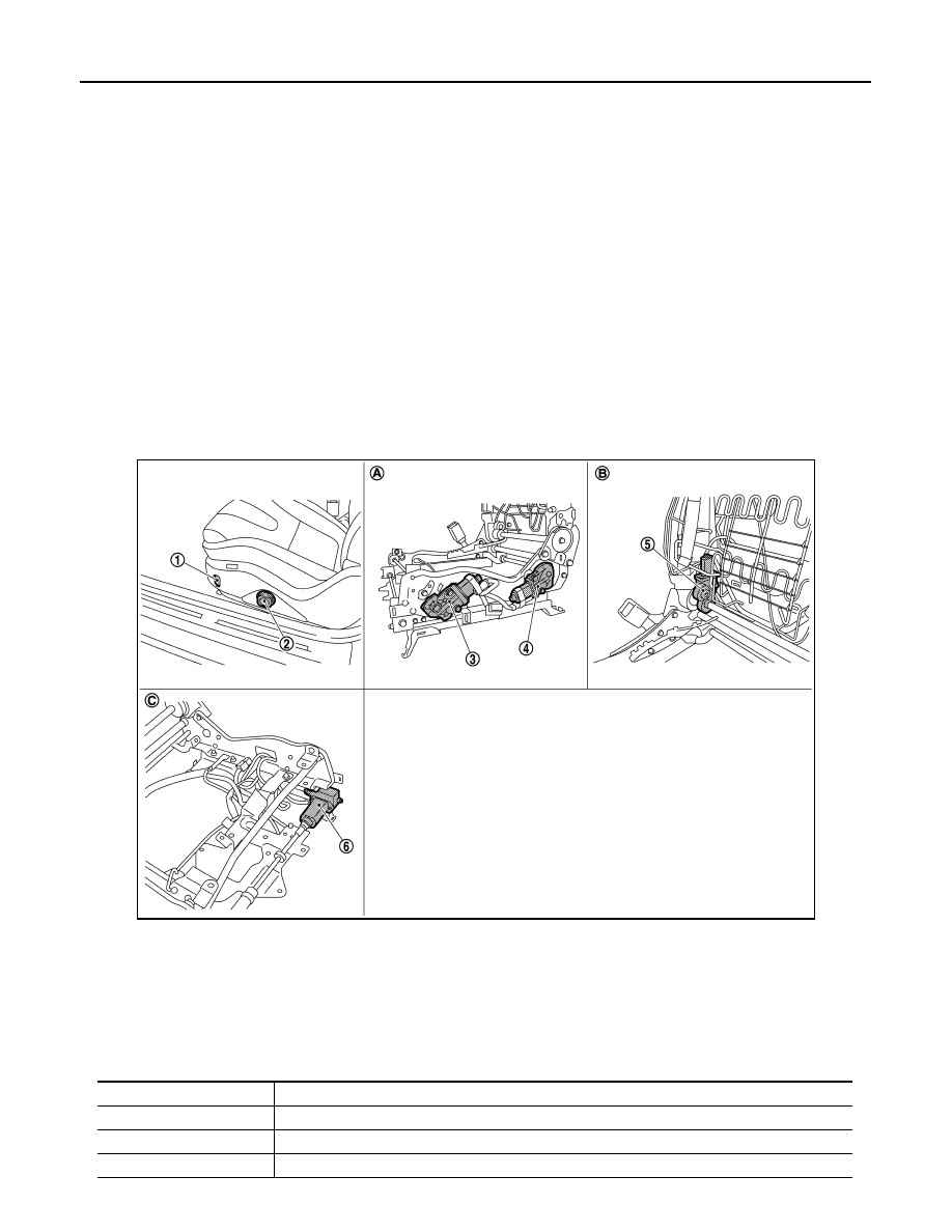
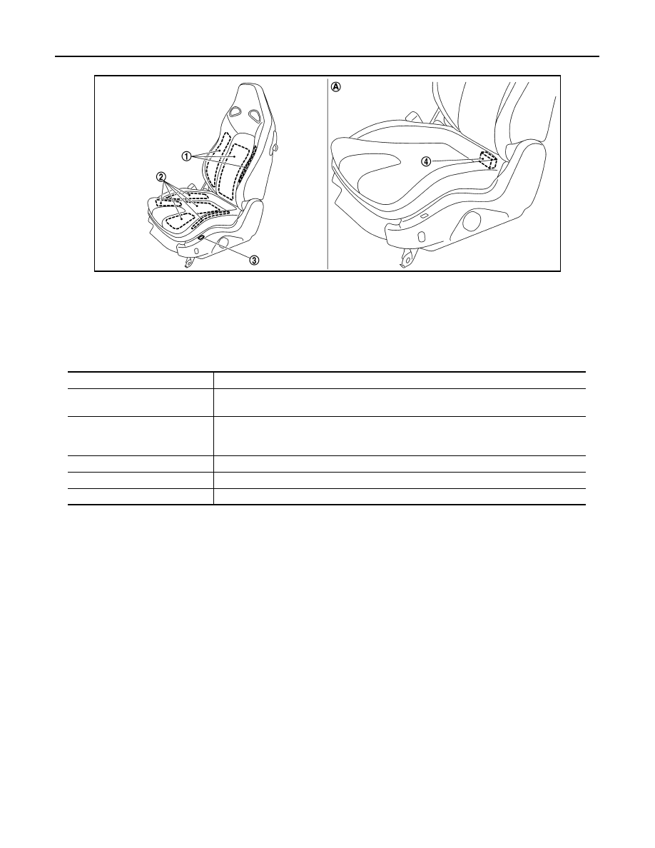
Component Parts Location
INFOID:0000000009162892
Component Description
INFOID:0000000009162893
JMJIA5200ZZ
1.
Thigh support switch
2.
Power seat switch (driver side)
3.
Thigh support motor
4.
Lifting motor (rear)
5.
Reclining motor
6.
Sliding motor
A.
Behind the seat cushion outer finish-
er outside
B.
Built in seatback
C.
Built in seat cushion
Item
Function
Power seat switch
Built-in reclining switch, sliding switch and lifting switch, controls the power supplied to each motor.
Thigh support switch
Detect the operation of thigh support motor.
Lifting motor
Operates seat lift up and down.
2014 GT-R
POWER SEAT FOR DRIVER SIDE
SE-5
< SYSTEM DESCRIPTION >
C
D
E
F
G
H
I
K
L
M
A
B
SE
N
O
P
Reclining motor
With the power supplied to power seat switch, operates the forward and backward of seat back.
Sliding motor
With the power supplied to power seat switch, operates the forward and backward slide of seat.
Thigh support motor
Operates the front portion of seat cushion up and down.
Item
Function
2014 GT-R
SE-6
< SYSTEM DESCRIPTION >
POWER SEAT FOR PASSENGER SIDE
POWER SEAT FOR PASSENGER SIDE
System Description
INFOID:0000000009162894
SLIDING OPERATION
• While operating the sliding switch located in power seat switch, sliding motor operates and makes possible
the seat forward and backward position adjustment.
RECLINING OPERATION
While operating the reclining switch located in power seat switch, reclining motor operates and makes possi-
ble the seatback forward and backward position adjustment.
Component Parts Location
INFOID:0000000009162895
Component Description
INFOID:0000000009162896
JMJIA5201ZZ
1.
Power seat switch
2.
Reclining motor
3.
Sliding motor
4.
Sliding relay (backward)
5.
Sliding relay (forward)
A.
Built in seatback
B.
Built in seat cushion
C.
Back side of seat cushion
Item
Function
Power seat switch
Built-in reclining switch and sliding switch controls the power supplied to each motor.
Sliding switch
Detect the operation of sliding motor.
Reclining motor
With the power supplied to power seat switch, operates the forward and backward of seatback.
Sliding motor
With the power supplied to power seat switch, operates the forward and backward slide of seat.
2014 GT-R
HEATED SEAT (DRIVER SIDE)
SE-7
< SYSTEM DESCRIPTION >
C
D
E
F
G
H
I
K
L
M
A
B
SE
N
O
P
HEATED SEAT (DRIVER SIDE)
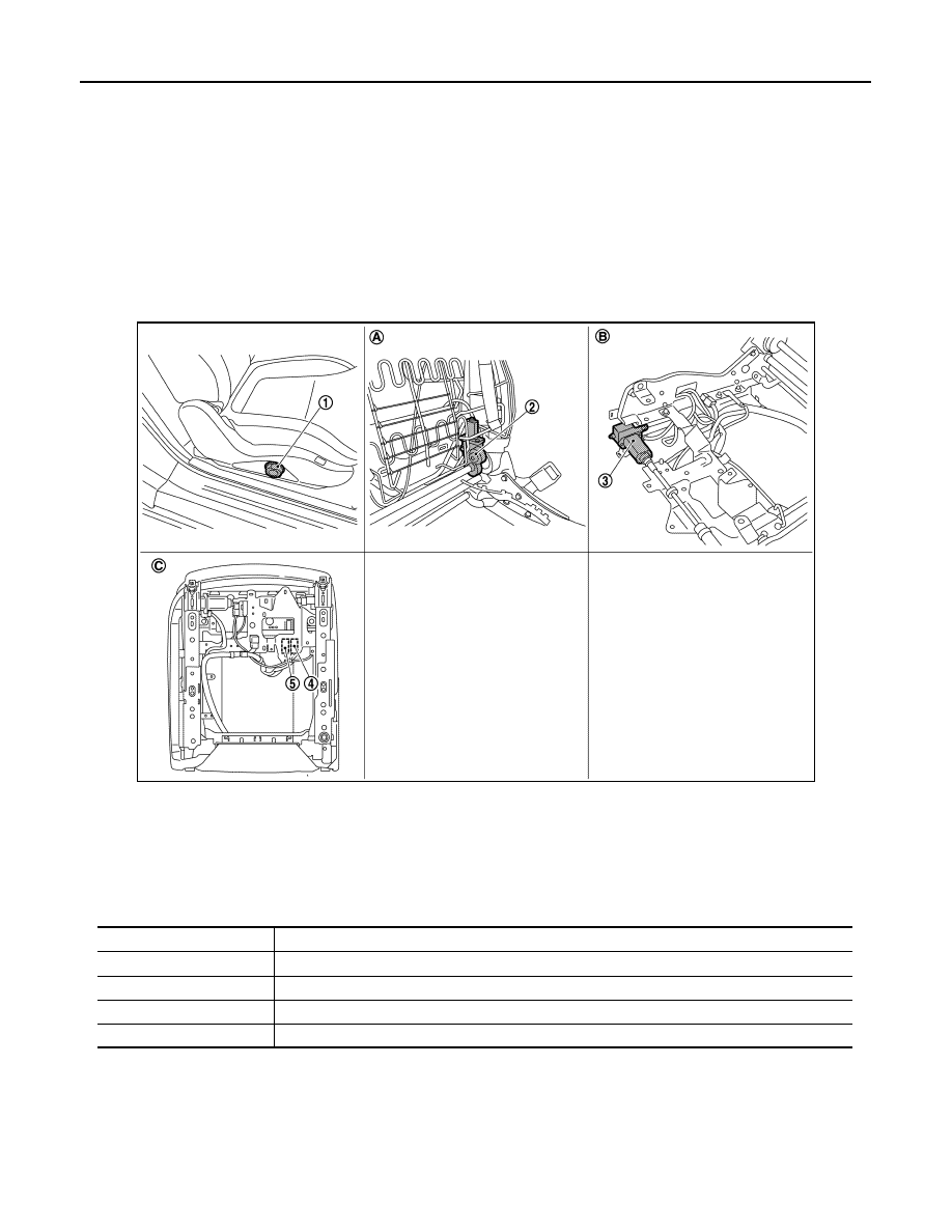
System Diagram
INFOID:0000000009162897
System Description
INFOID:0000000009162898
• Heated seat is activated by heated seat switch while ignition switch is ON, and is equipped with the function
to warm seat cushion and seatback.
• Heated seat is equipped with the LO/HI temperature adjustment function that adjusts temperature by operat-
ing heated seat switch to the optimal position.
OPERATION DESCRIPTION
• When operating heated seat switch to either position of LO/HI while ignition switch is ON, indicator illumi-
nates, heated seat control unit supplies power supply to heater unit, and warms seat cushion and seatback.
• Heat sensor that is built in seat cushion heater detects seat cushion heater temperature and outputs to
heated seat control unit.
• Heated seat control unit monitors the heated seat switch position and heater sensor temperature, and inter-
rupts power supply to heater unit when the heat sensor temperature reaches preset temperature.
JMJIA5207GB
2014 GT-R
SE-8
< SYSTEM DESCRIPTION >
HEATED SEAT (DRIVER SIDE)
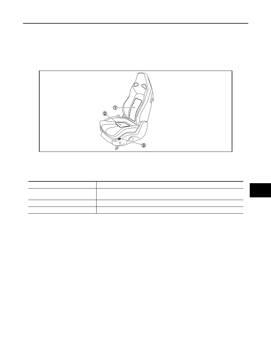
Component Parts Location
INFOID:0000000009162899
Component Description
INFOID:0000000009162900
JMJIA5202ZZ
1.
seatback heater
2.
Seat cushion heater
3.
Heated seat switch
4.
Heated seat control unit
A.
Back side of seat cushion
Item
Function
Heated seat control unit
• Activates seat cushion heater and seatback heater via heated seat switch signal.
• Controls heated seat system.
Heated seat switch
• Supplies power supply to each heater.
• Equips indicator that indicates the operating condition.
• Changes the number of activated heaters depending on the HI or LO switch position.
Heat sensor
Outputs seat cushion temperature to heated seat control unit
Seat cushion heater
Built in seatback and is activated by power supply from heated seat switch.
Seatback heater
Built in seatback and is activated by power supply from heated seat switch.
2014 GT-R
HEATED SEAT (PASSENGER SIDE)
SE-9
< SYSTEM DESCRIPTION >
C
D
E
F
G
H
I
K
L
M
A
B
SE
N
O
P
HEATED SEAT (PASSENGER SIDE)
System Description
INFOID:0000000009162901
• By turning seat heated switch ON, seat cushion heater and seat back heater are activated.
• By switching seat switch to HI or LO, the number of activated heaters changes and seat warming seed is
adjusted.
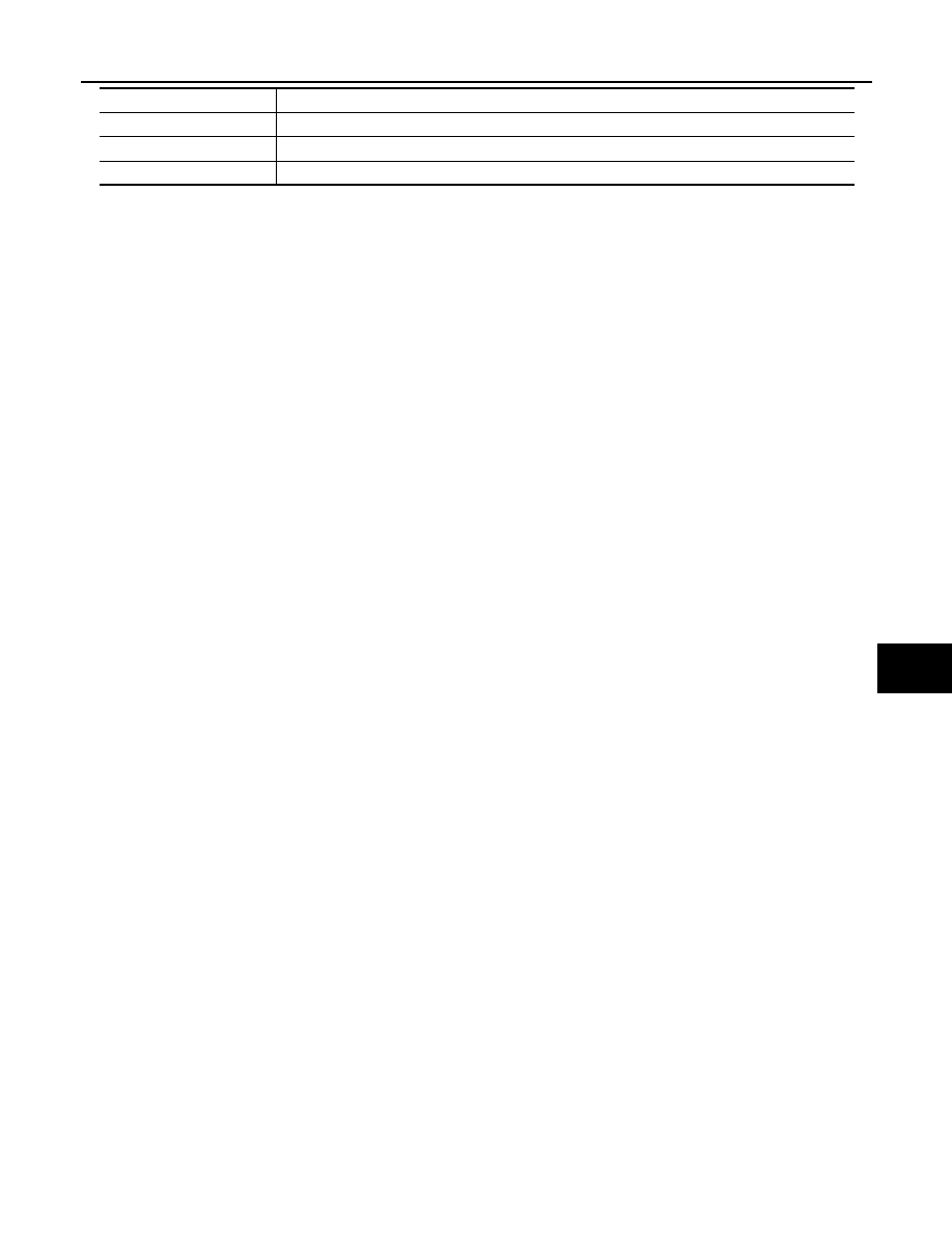
Component Parts Location
INFOID:0000000009162902
Component Description
INFOID:0000000009162903
JMJIA5846ZZ
1.
Seat back heater
2.
Seat cushion heater
3.
Heated seat switch
Item
Function
Heated seat switch
• Supplies power supply to each heater.
• Changes the number of activated heaters depending on the HI or LO switch position.
Seat cushion heater
Built in seat cushion and is activated by power supply from heated seat switch.
Seat back heater
Built in seat back and is activated by power supply from heated seat switch.
2014 GT-R
SE-10
< ECU DIAGNOSIS INFORMATION >
HEATED SEAT CONTROL UNIT (DRIVER SIDE)
ECU DIAGNOSIS INFORMATION
HEATED SEAT CONTROL UNIT (DRIVER SIDE)
Reference Value
INFOID:0000000009162904
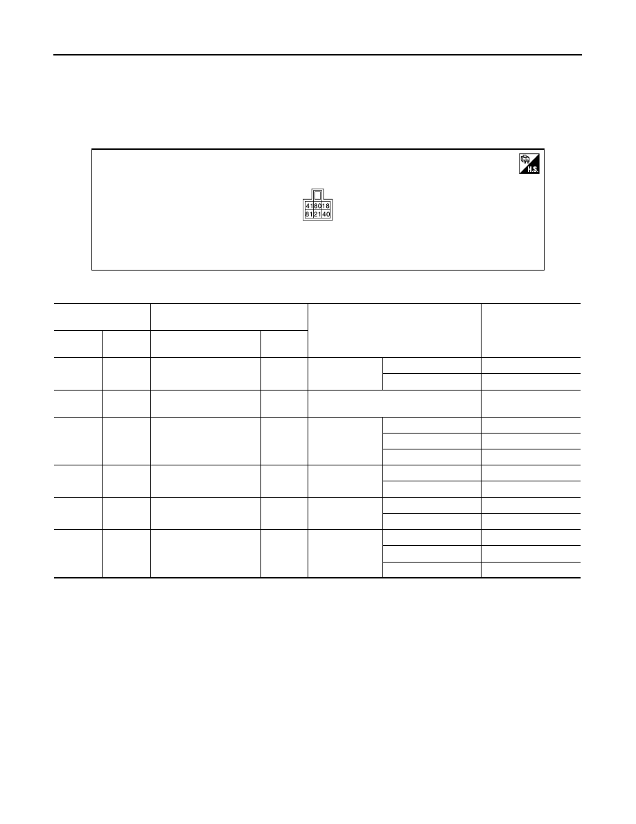
TERMINAL LAYOUT
PHYSICAL VALUES
*: Voltage is repeated within the value shown as per the following list depending on heater unit temperature.
JMJIA5044ZZ
Terminal No.
(Wire color)
Description
Condition
Voltage (V)
(Approx.)
(+)
(–)
Signal name
Input/
Output
18
(R)
Ground
IGN power supply
Input
Ignition switch
OFF or ACC
0
ON
Battery voltage
21
(B)
Ground
Ground
–
Ignition switch ON
0
40
(W)
Ground
Heat sensor signal
Input
Heated seat
switch
OFF
0
OL
10.87 – 11.02*
HI
11.31 – 11.43*
41
(R/W)
Ground
Seat cushion heater pow-
er supply
Output
Heated seat
Operate
0 – Battery voltage*
Other than above
0
80
(L/W)
Ground
Heated seat operation sig-
nal
Input
Heated seat
Operate
Battery voltage
Other than above
0
81
(R/L)
Ground
Heated seat switch signal
Input
Heated seat
switch
OFF
0
OL
12.24
HI
12.90
2014 GT-R
POWER SEAT FOR DRIVER SIDE
SE-11
< WIRING DIAGRAM >
C
D
E
F
G
H
I
K
L
M
A
B
SE
N
O
P
WIRING DIAGRAM
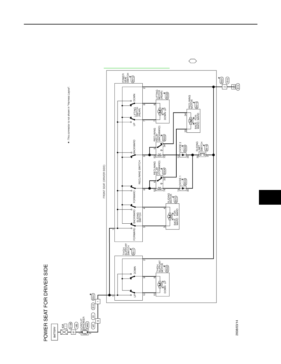
POWER SEAT FOR DRIVER SIDE
Wiring Diagram - POWER SEAT FOR DRIVER SIDE -
INFOID:0000000009162905
For connector terminal arrangements, harness layouts, and alphabets in a
(option abbreviation; if not
described in wiring diagram), refer to
GI-12, "Connector Information"
JCJWA0439GB
2014 GT-R
SE-12
< WIRING DIAGRAM >
POWER SEAT FOR PASSENGER SIDE
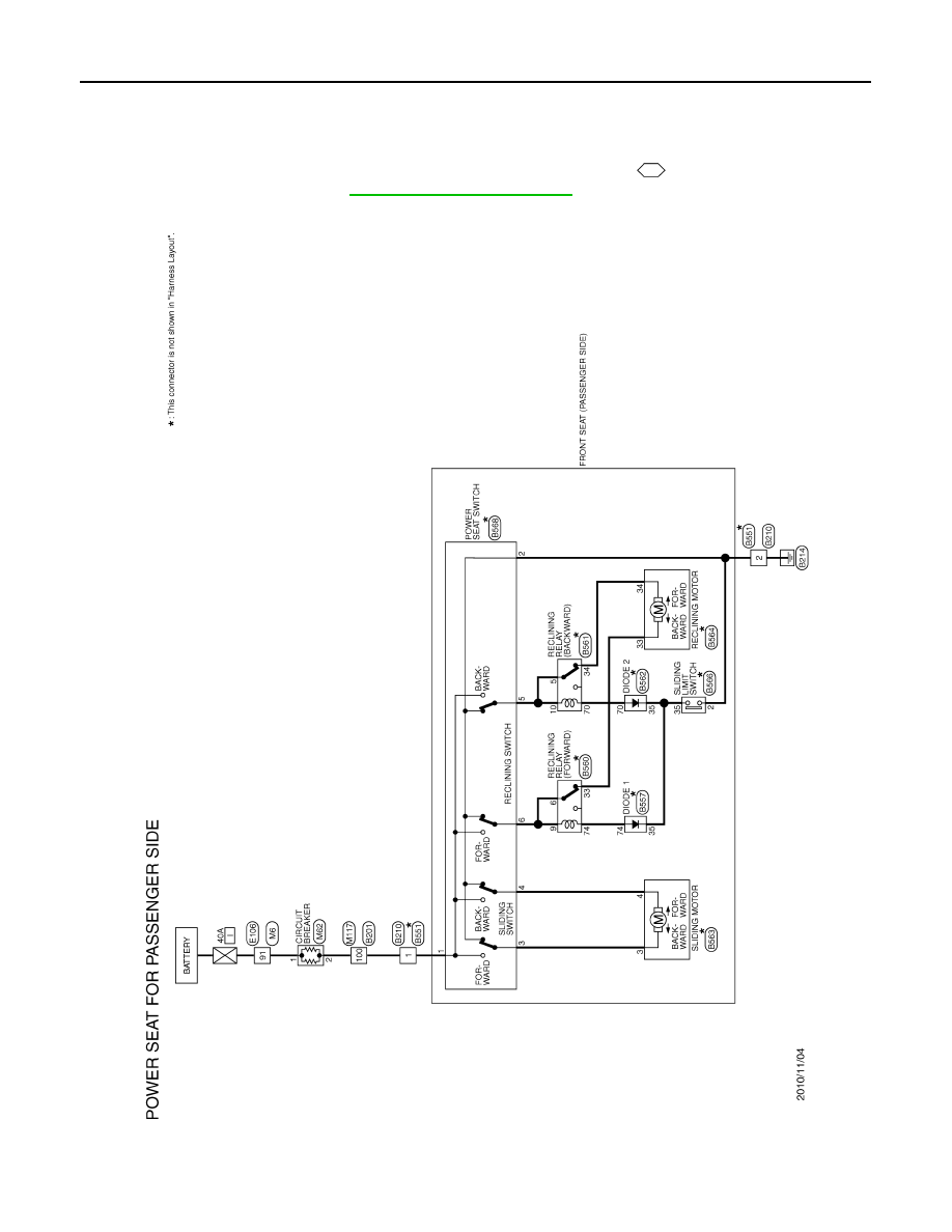
POWER SEAT FOR PASSENGER SIDE
Wiring Diagram - POWER SEAT FOR PASSENGER SIDE -
INFOID:0000000009162906
For connector terminal arrangements, harness layouts, and alphabets in a
(option abbreviation; if not
described in wiring diagram), refer to
GI-12, "Connector Information"
JCJWA1374GB
2014 GT-R
HEATED SEAT
SE-13
< WIRING DIAGRAM >
C
D
E
F
G
H
I
K
L
M
A
B
SE
N
O
P
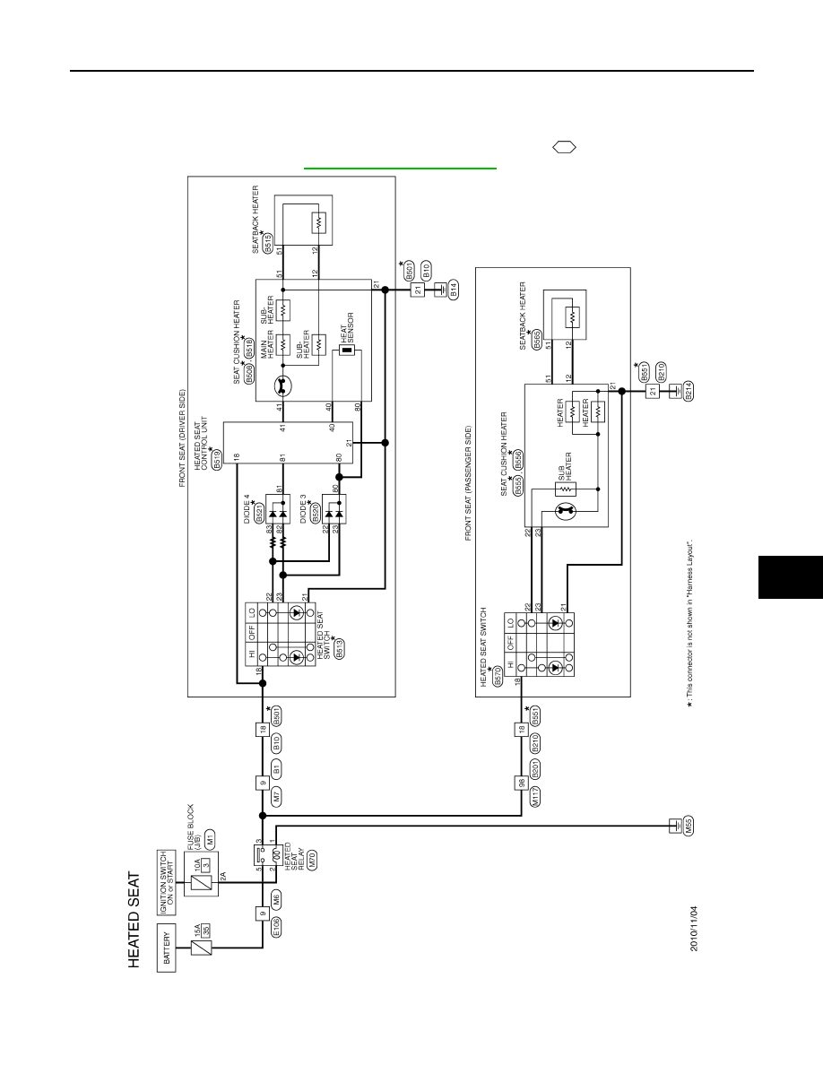
HEATED SEAT
Wiring Diagram - HEATED SEAT -
INFOID:0000000009162907
For connector terminal arrangements, harness layouts, and alphabets in a
(option abbreviation; if not
described in wiring diagram), refer to
GI-12, "Connector Information"
JCJWA1378GB
2014 GT-R
SE-14
< DTC/CIRCUIT DIAGNOSIS >
POWER SUPPLY AND GROUND CIRCUIT
DTC/CIRCUIT DIAGNOSIS
POWER SUPPLY AND GROUND CIRCUIT
HEATED SEAT CONTROL UNIT
HEATED SEAT CONTROL UNIT : Diagnosis Procedure
INFOID:0000000009162908
1.
CHECK FUSE
Check that the following fuse is not fusing.
Is the inspection result normal?
YES
>> GO TO 2.
NO
>> Replace the blown fuse after repairing the affected circuit if a fuse is blown.
2.
CHECK POWER SUPPLY
1.
Turn ignition switch OFF.
2.
Disconnect heated seat control unit connector.
3.
Turn ignition switch ON.
4.
Check voltage between heated seat control unit harness connector and ground.
Is the inspection result normal?
YES
>> GO TO 4.
NO
>> GO TO 3.
3.
CHECK POWER SUPPLY CIRCUIT
1.
Turn ignition switch OFF.
2.
Disconnect heated seat relay connector.
3.
Check continuity between heated seat control unit harness connector and heated seat relay terminal con-
nector.
4.
Check continuity between heated seat control unit harness connector and ground.
Is the inspection result normal?
YES
>> Check heated seat relay. Refer to
SE-20, "Component Function Check"
NO
>> Repair or replace harness.
4.
CHECK GROUND CIRCUIT
1.
Turn ignition switch OFF.
2.
Check continuity between heated seat control unit harness connector and ground.
Signal name
Fuse No.
Battery power supply
35 (15 A)
(+)
(
−
)
Voltage (V)
(Approx.)
Heated seat control unit
Connector
Terminal
B519
18
Ground
Battery voltage
Heated seat control unit
Heated seat relay
Continuity
Connector
Terminal
Connector
Terminal
B519
18
M70
3
Existed
Heated seat control unit
Ground
Continuity
Connector
Terminal
B519
18
Not existed
2014 GT-R
POWER SUPPLY AND GROUND CIRCUIT
SE-15
< DTC/CIRCUIT DIAGNOSIS >
C
D
E
F
G
H
I
K
L
M
A
B
SE
N
O
P
Is the inspection result normal?
YES
>> Replace heated seat control unit.
NO
>> Repair or replace harness.
HEATED SEAT SWITCH (DRIVER SIDE)
HEATED SEAT SWITCH (DRIVER SIDE) : Diagnosis Procedure
INFOID:0000000009162909
1.
CHECK FUSE
Check that the following fuse is not fusing.
Is the inspection result normal?
YES
>> GO TO 2.
NO
>> Replace the blown fuse after repairing the affected circuit if a fuse is blown.
2.
CHECK POWER SUPPLY
1.
Turn ignition switch OFF.
2.
Disconnect heated seat switch connector.
3.
Turn ignition switch ON.
4.
Check voltage between heated seat switch harness connector and ground.
Is the inspection result normal?
YES
>> GO TO 4.
NO
>> GO TO 3.
3.
CHECK POWER SUPPLY CIRCUIT
1.
Turn ignition switch OFF.
2.
Disconnect heated seat relay connector.
3.
Check continuity between heated seat switch harness connector and heated seat relay terminal connec-
tor.
4.
Check continuity between heated seat switch harness connector and ground.
Is the inspection result normal?
YES
>> Check heated seat relay. Refer to
SE-20, "Component Function Check"
.
NO
>> Repair or replace harness.
4.
CHECK INTERMITTENT INCIDENT
Heated seat control unit
Ground
Continuity
Connector
Terminal
B519
21
Existed
Signal name
Fuse No.
Battery power supply
35 (15 A)
(+)
(
−
)
Voltage (V)
(Approx.)
Heated seat switch
Connector
Terminal
Driver side
B513
18
Ground
Battery voltage
Heated seat switch
Heated seat relay
Continuity
Connector
Terminal
Connector
Terminal
Driver side
B513
18
M70
3
Existed
Heated seat switch
Ground
Continuity
Connector
Terminal
Driver side
B513
18
Not existed
2014 GT-R
SE-16
< DTC/CIRCUIT DIAGNOSIS >
POWER SUPPLY AND GROUND CIRCUIT
Check intermittent incident.
Refer to
GI-38, "Intermittent Incident"
>> INSPECTION END
2014 GT-R
Нет комментариевНе стесняйтесь поделиться с нами вашим ценным мнением.
Текст