Nissan Almera Tino V10 (2001 year). Manual — part 128

DOOR LOCK/UNLOCK SWITCH CHECK
=NLEL0477S04
1
CHECK DOOR LOCK/UNLOCK SWITCH INPUT SIGNAL
1. Disconnect time control unit harness connector.
2. Check continuity between time control unit harness connector terminal 37 or 38 and ground.
NEL674
Refer to wiring diagram.
OK or NG
OK
©
Door lock/unlock switch is OK.
NG
©
GO TO 2.
2
CHECK DOOR LOCK/UNLOCK SWITCH
1. Disconnect door lock/unlock switch harness connector.
2. Check continuity between each door lock/unlock switch terminals.
+
Power window main switch (Door lock/unlock switch)
NEL684
OK or NG
OK
©
Check the following.
+
Ground circuit for door lock/unlock switch
+
Harness for open or short between door lock/unlock switch and time control unit con-
nector
NG
©
Replace door lock/unlock switch.
POWER DOOR LOCK — SUPER LOCK —
Trouble Diagnoses/RHD Models (Cont’d)
EL-303

DOOR KEY CYLINDER SWITCH CHECK
NLEL0477S05
1
CHECK DOOR KEY CYLINDER SWITCH INPUT SIGNAL (LOCK/UNLOCK SIGNAL)
Check voltage between time control unit harness connector terminals 28 or 29 and ground.
NEL685
Refer to wiring diagram.
OK or NG
OK
©
Door key cylinder switch is OK.
NG
©
GO TO 2.
2
CHECK DOOR KEY CYLINDER SWITCH
1. Disconnect door key cylinder switch harness connector.
2. Check continuity between door key cylinder switch terminals.
NEL686
OK or NG
OK
©
Check the following.
+
Door key cylinder switch ground circuit
+
Harness for open or short between time control unit and door key cylinder switch
NG
©
Replace door key cylinder switch.
POWER DOOR LOCK — SUPER LOCK —
Trouble Diagnoses/RHD Models (Cont’d)
EL-304

DOOR LOCK ACTUATOR CHECK
NLEL0477S06
1
CHECK DOOR LOCK ACTUATOR OUTPUT SIGNAL
Check voltage for door lock actuator.
+
Door lock actuator driver’s side
NEL678
+
Door lock actuator passenger side and rear
NEL679
Refer to wiring diagram.
OK or NG
OK
©
GO TO 2.
NG
©
Replace time control unit. (Before replacing the control unit, perform “DOOR LOCK/
UNLOCK SWITCH CHECK”.)
POWER DOOR LOCK — SUPER LOCK —
Trouble Diagnoses/RHD Models (Cont’d)
EL-305

2
CHECK DOOR LOCK ACTUATOR
1. Disconnect door lock actuator harness connector.
2. Apply 12V direct current to door lock actuator and check operation.
a. Front and rear door
(Models with fuse and fusible link box E43)
NEL687
b. Front and rear door
(Models with fuse and fusible link box E90)
NEL774
c. Back door
NEL681
OK or NG
OK
©
Check harness for open or short between time control unit connector and door lock
actuator.
NG
©
Replace door lock actuator.
POWER DOOR LOCK — SUPER LOCK —
Trouble Diagnoses/RHD Models (Cont’d)
EL-306

SUPER LOCK ACTUATOR CHECK
NLEL0477S07
1
CHECK OUTPUT SIGNAL FOR SUPER LOCK ACTUATOR
Check voltage for super lock actuator.
NEL688
Refer to wiring diagram.
OK or NG
OK
©
GO TO 2.
NG
©
Replace time control unit. (Before replacing the unit, perform “DOOR KEY CYLINDER
SWITCH CHECK”.)
POWER DOOR LOCK — SUPER LOCK —
Trouble Diagnoses/RHD Models (Cont’d)
EL-307

2
CHECK SUPER LOCK ACTUATOR
1. Disconnect door lock actuator assembly connector.
2. Set lever A in lock position.
3. Apply 12V direct current to door lock actuator assembly and check operation.
Models with fuse and fusible link box E43
NEL689
Models with fuse and fusible link box E90
NEL775
OK or NG
OK
©
Check harness for open or short between time control unit and super lock actuator.
NG
©
Replace super lock actuator.
POWER DOOR LOCK — SUPER LOCK —
Trouble Diagnoses/RHD Models (Cont’d)
EL-308

DOOR SWITCH CHECK
NLEL0477S08
1
CHECK DOOR SWITCH INPUT SIGNAL
Check voltage between time control unit harness connector terminals 6 and ground.
NEL647
Refer to wiring diagram.
OK or NG
OK
©
Door switch is OK.
NG
©
GO TO 2.
2
CHECK DOOR SWITCH
1. Disconnect door switch harness connector.
2. Check continuity between door switch terminals.
NEL648
OK or NG
OK
©
Check the following.
+
Door switch ground circuit or door switch ground condition
+
Harness for open or short between smart entrance control unit and door switch
NG
©
Replace door switch.
POWER DOOR LOCK — SUPER LOCK —
Trouble Diagnoses/RHD Models (Cont’d)
EL-309
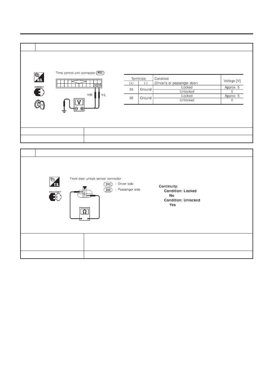
DOOR UNLOCK SENSOR CHECK
NLEL0477S13
1
CHECK DOOR UNLOCK SENSOR INPUT SIGNAL
Check voltage between time control unit terminal 35 or 36 and ground.
NEL682
Refer to wiring diagram.
OK or NG
OK
©
Door unlock sensor is OK.
NG
©
GO TO 2.
2
CHECK DOOR UNLOCK SENSOR
1. Disconnect door unlock sensor connector.
2. Check continuity between door unlock sensor terminals 2 and 5.
NEL690
OK or NG
OK
©
Check the following.
+
Door unlock sensor ground circuit
+
Harness for open or short between time control unit and door unlock sensor
NG
©
Replace door unlock sensor.
POWER DOOR LOCK — SUPER LOCK —
Trouble Diagnoses/RHD Models (Cont’d)
EL-310

NATS RELEASE SIGNAL CHECK
NLEL0477S09
1
CHECK NATS SIGNAL CIRCUIT
1. Disconnect battery cable (−) terminal.
2. Disconnect time control unit connector and NATS IMMU connector.
NEL691
OK or NG
OK
©
GO TO 2.
NG
©
Repair harness.
2
CHECK NATS RELEASE SIGNAL
1. Connect time control unit connector and NATS IMMU connector.
2. Connect battery cable (−) terminal.
3. Check voltage between time control unit terminal 26 and ground.
NEL692
OK or NG
OK
©
Replace super lock control unit.
NG
©
Check NATS system.
POWER DOOR LOCK — SUPER LOCK —
Trouble Diagnoses/RHD Models (Cont’d)
EL-311

KEY SWITCH (INSERT) CHECK
NLEL0477S10
1
CHECK KEY SWITCH INPUT SIGNAL
Check voltage between time control unit terminal 22 and ground.
NEL653
Refer to wiring diagram.
OK or NG
OK
©
Key switch is OK.
NG
©
GO TO 2.
2
CHECK KEY SWITCH (INSERT)
Check continuity between key switch terminals 1 and 2.
NEL787
OK or NG
OK
©
Check the following.
+
10A fuse [No. 12, located in fuse block (J/B)]
+
Harness for open or short between key switch and fuse
+
Harness for open or short between time control unit and key switch
NG
©
Replace key switch.
POWER DOOR LOCK — SUPER LOCK —
Trouble Diagnoses/RHD Models (Cont’d)
EL-312

IGNITION SWITCH “ON” CIRCUIT CHECK
NLEL0477S11
1
CHECK IGNITION ON SIGNAL
Check voltage between time control unit terminal 1 and ground.
NEL646
OK or NG
OK
©
Ignition switch “ON” circuit is OK.
NG
©
Check the following.
+
10A fuse [No. 10, located in fuse block (J/B)]
+
Harness for open or short between time control unit and fuse
REMOTE CONTROLLER SIGNAL CHECK
NLEL0477S12
1
CHECK OUTPUT SIGNAL FOR SUPER LOCK ACTUATOR BY MULTI-REMOTE CONTROLLER
1. Withdraw key from ignition key cylinder.
2. Check voltage between time control unit terminal 40 or 44 and ground.
NEL693
OK or NG
OK
©
System is OK.
NG
©
Replace time control unit. (Before replacing the unit, make sure the remote controller ID
registration for time control unit and the remote controller battery once again.)
POWER DOOR LOCK — SUPER LOCK —
Trouble Diagnoses/RHD Models (Cont’d)
EL-313
System Description
NLEL0480
FUNCTION
NLEL0480S01
Multi-remote control system has the following function.
+
Door lock (and set super lock)
+
Door unlock (and release super lock)
+
Hazard reminder
LOCK OPERATION
NLEL0480S02
To lock door by multi-remote controller, the key switch must be at OFF.
When the LOCK signal is input to time control unit (the antenna of the system is combined with time control
unit)
Then time control unit controls to lock doors and set super lock (models with super lock).
UNLOCK OPERATION
NLEL0480S03
When the UNLOCK signal is input to time control unit (the antenna of the system is combined with time con-
trol unit)
Time control unit controls to unlock driver’s door and release super lock (models with super lock).
Then, if an unlock signal is sent from the remote controller again within 5 seconds, all other doors will be
unlocked.
HAZARD REMINDER
NLEL0480S04
When the doors are locked or unlocked by multi-remote controller, supply power to turn lamps hazard reminder
flashes as follows
+
Lock operation: Flash once
+
Unlock operation: Flash twice
MULTI-REMOTE CONTROLLER ID CODE ENTRY
NLEL0480S05
A maximum of four remote controllers can be entered.
To enter ID code entry, the following signals must be input to the time control unit.
+
Ignition switch (ON)
+
Signal from remote controller
For detailed procedure, refer to “ID Code Entry Procedure” in EL-324.
MULTI-REMOTE CONTROL SYSTEM
System Description
EL-314
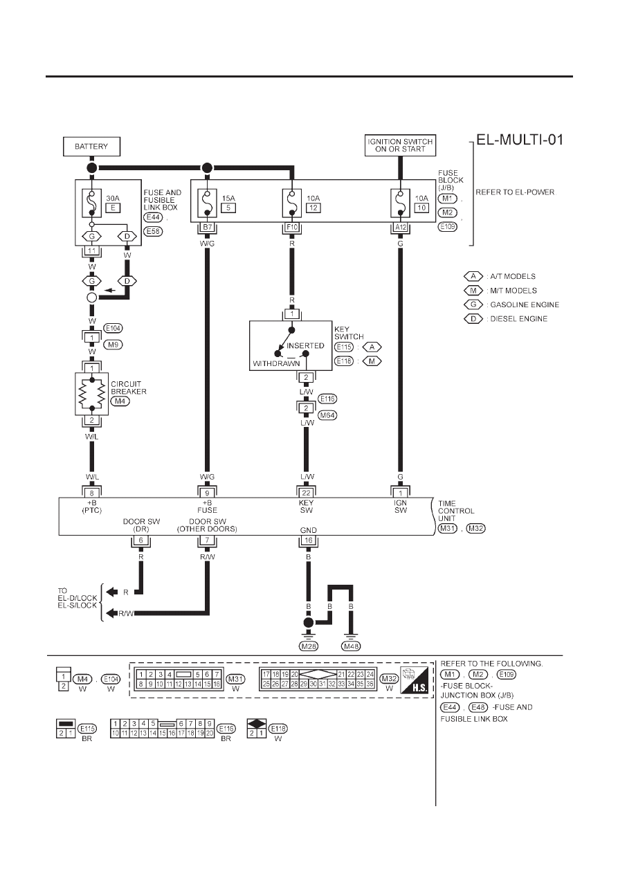
Wiring Diagram — MULTI —
NLEL0481
MODELS WITH FUSE AND FUSIBLE LINK BOX E43
NLEL0481S03
Fig. 1
NLEL0481S0301
YEL947B
MULTI-REMOTE CONTROL SYSTEM
Wiring Diagram — MULTI —
EL-315

Fig. 2
NLEL0481S0302
YEL948B
MULTI-REMOTE CONTROL SYSTEM
Wiring Diagram — MULTI — (Cont’d)
EL-316
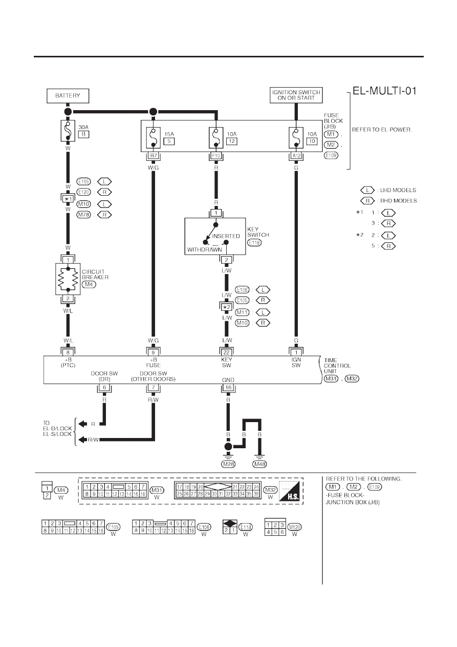
MODELS WITH FUSE AND FUSIBLE LINK BOX E90
NLEL0481S05
Fig. 1
NLEL0481S0501
YEL484C
MULTI-REMOTE CONTROL SYSTEM
Wiring Diagram — MULTI — (Cont’d)
EL-317

Fig. 2
NLEL0481S0502
YEL485C
MULTI-REMOTE CONTROL SYSTEM
Wiring Diagram — MULTI — (Cont’d)
EL-318
Нет комментариевНе стесняйтесь поделиться с нами вашим ценным мнением.
Текст