Nissan Murano (2022 year). Manual in english — page 12

CONDITIONS THE REMOTE ENGINE
START WILL NOT WORK
The Remote Engine Start will not operate if
any of the following conditions are present:
• The ignition switch is placed in the ON
position.
• The hood is not securely closed.
• The hazard indicator lights are on.
• The engine is still running. The engine
must be completely stopped. Wait at
least 6 seconds if the engine goes from
running to off. This is not applicable when
extending engine run time.
• The
button is not pressed and held
for at least 2 seconds.
• The
button is not pressed and held
within 5 seconds of pressing the lock
button.
• The brake is pressed.
• The doors are not closed and locked.
• The liftgate is open.
• The Key System Fault warning light re-
mains solid is in the vehicle information
display.
• The alarm sounds due to illegal entry into
the vehicle.
• Two Remote Engine Starts, or a single
Remote Engine Start with an extension,
have already been used.
• The vehicle is not in P (Park).
• There is a detected registered key already
inside of the vehicle.
• The Remote Engine Start function has
been switched to the OFF position in Ve-
hicle Settings of the vehicle information
display. For additional information, see
“Vehicle information display” (P. 2-16).
The Remote Engine Start may display a
warning or indicator in the vehicle informa-
tion display. For additional information, see
“Vehicle information display” (P. 2-16).
3-20
Pre-driving checks and adjustments
-------------------------------------------------------------------------------------------------------------------------------------------------------------
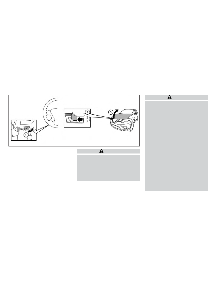
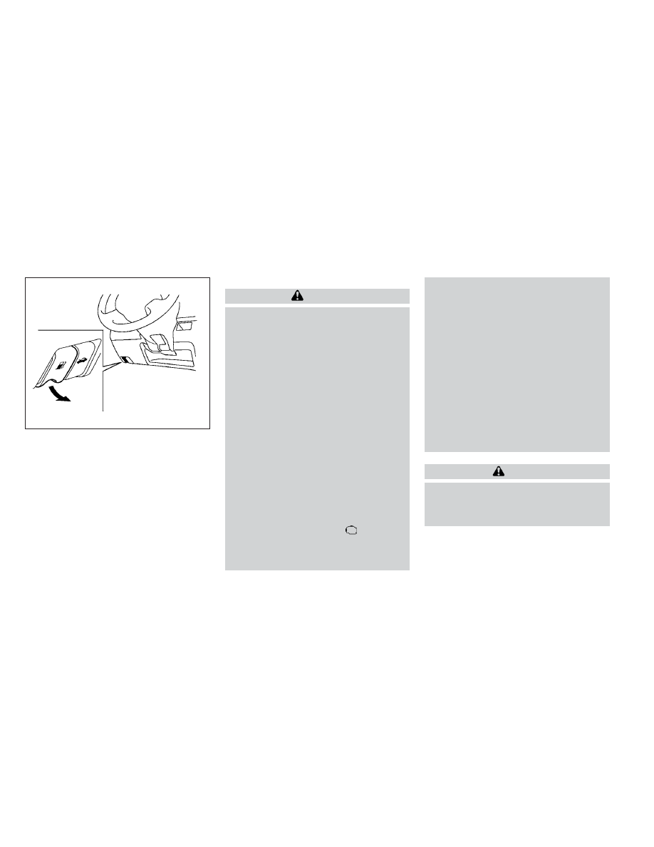
1. Pull the hood lock release handle
O
1
lo-
cated below the driver side instrument
panel until the hood springs up slightly.
2. Locate the lever
O
2
in between the hood
and grille and push the lever sideways
with your fingertips and raise the hood
O
3
.
When closing the hood, lower the hood to
approximately 12 in (30 cm) above the latch
and release it. This allows proper engage-
ment of the hood latch.
WARNING
•
Make sure the hood is completely
closed and latched before driving.
Failure to do so could cause the hood
to fly open and result in an accident.
•
If you see steam or smoke coming
from the engine compartment, to
avoid injury do not open the hood.
WARNING
•
Always be sure the liftgate has been
closed securely to prevent it from
opening while driving.
•
Do not drive with the liftgate open.
This could allow dangerous exhaust
gases to be drawn into the vehicle.
For additional information, see “Ex-
haust
gas
(carbon
monoxide)”
(P. 5-4).
•
To help avoid risk of injury or death
through unintended operation of the
vehicle and/or its systems, including
entrapment in windows or inadver-
tent door lock activation, do not
leave children, people who require
the assistance of others or pets unat-
tended in your vehicle. Additionally,
the temperature inside a closed ve-
hicle on a warm day can quickly be-
come high enough to cause a signifi-
cant risk of injury or death to people
and pets.
•
Always be sure that hands and feet
are clear of the door frame to avoid
injury while closing the liftgate.
LPD3063
HOOD
LIFTGATE
Pre-driving checks and adjustments
3-21
-------------------------------------------------------------------------------------------------------------------------------------------------------------
CAUTION
Do not use accessory carriers that at-
tach to the liftgate. Doing so will cause
damage to the vehicle.
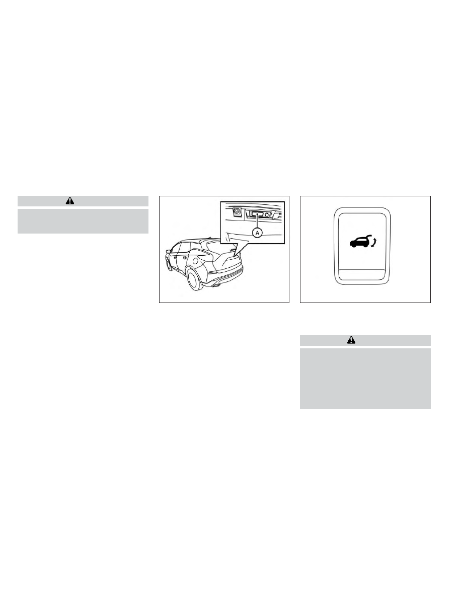
OPERATING THE MANUAL
LIFTGATE (if so equipped)
The power door lock system allows you to
lock or unlock all doors including the lift-
gate simultaneously.
To open the liftgate, push the liftgate
opener switch
O
A
and pull up on the
handle.
To close, lower and push the liftgate down
securely.
OPERATING THE POWER LIFTGATE
(if so equipped)
WARNING
•
Make sure that all passengers have
their hands, etc., inside the vehicle
before closing the liftgate.
•
Do not leave children unattended in-
side the vehicle. They could unknow-
ingly activate switches or controls.
Unattended children could become
involved in serious accidents.
LPD2318
LPD2212
Instrument panel switch
3-22
Pre-driving checks and adjustments
-------------------------------------------------------------------------------------------------------------------------------------------------------------
NOTE:
To open, close or reverse the power lift-
gate, the shift lever must be in P (Park).
Also, the power liftgate will not operate if
battery voltage is low.
Power Open:
The power liftgate automatically moves
from the fully closed position to the fully
open position in approximately 5 – 8 sec-
onds. The power open feature can be acti-
vated by the switch on the Intelligent Key,
the instrument panel switch, the liftgate
opener switch
O
A
. A chime sounds to indi-
cate the power open sequence has been
started.
• The liftgate can be opened by the instru-
ment panel switch, liftgate opener switch
O
A
with the Intelligent Key in operating
range and liftgate button on the key fob,
even if the vehicle is locked. The liftgate
will individually unlock and open. Once
the liftgate is closed, the vehicle will re-
main in the unlock status.
• The Intelligent Key button must be held
for 1 second before the liftgate opens.
• The liftgate must be unlocked to open it
with the liftgate opener switch
O
A
if the
Intelligent Key is not in operating range.
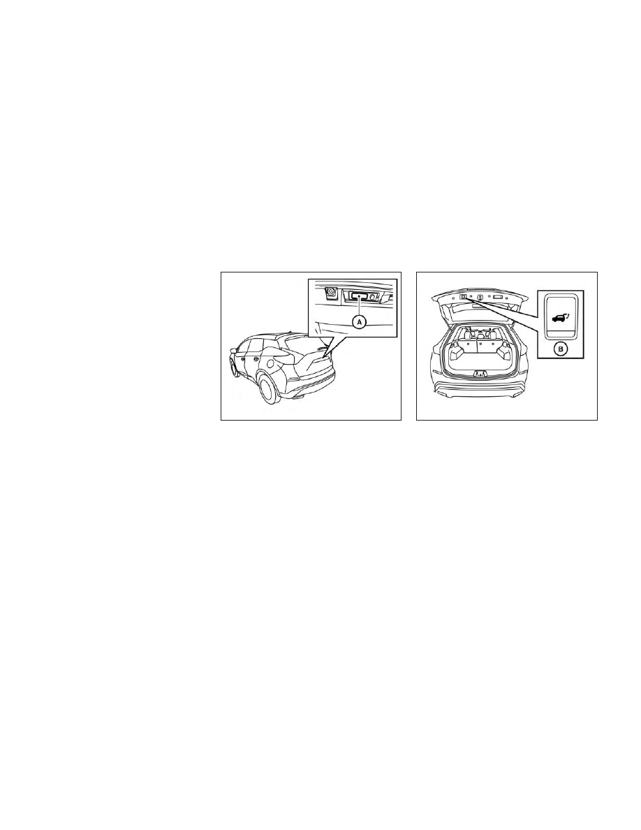
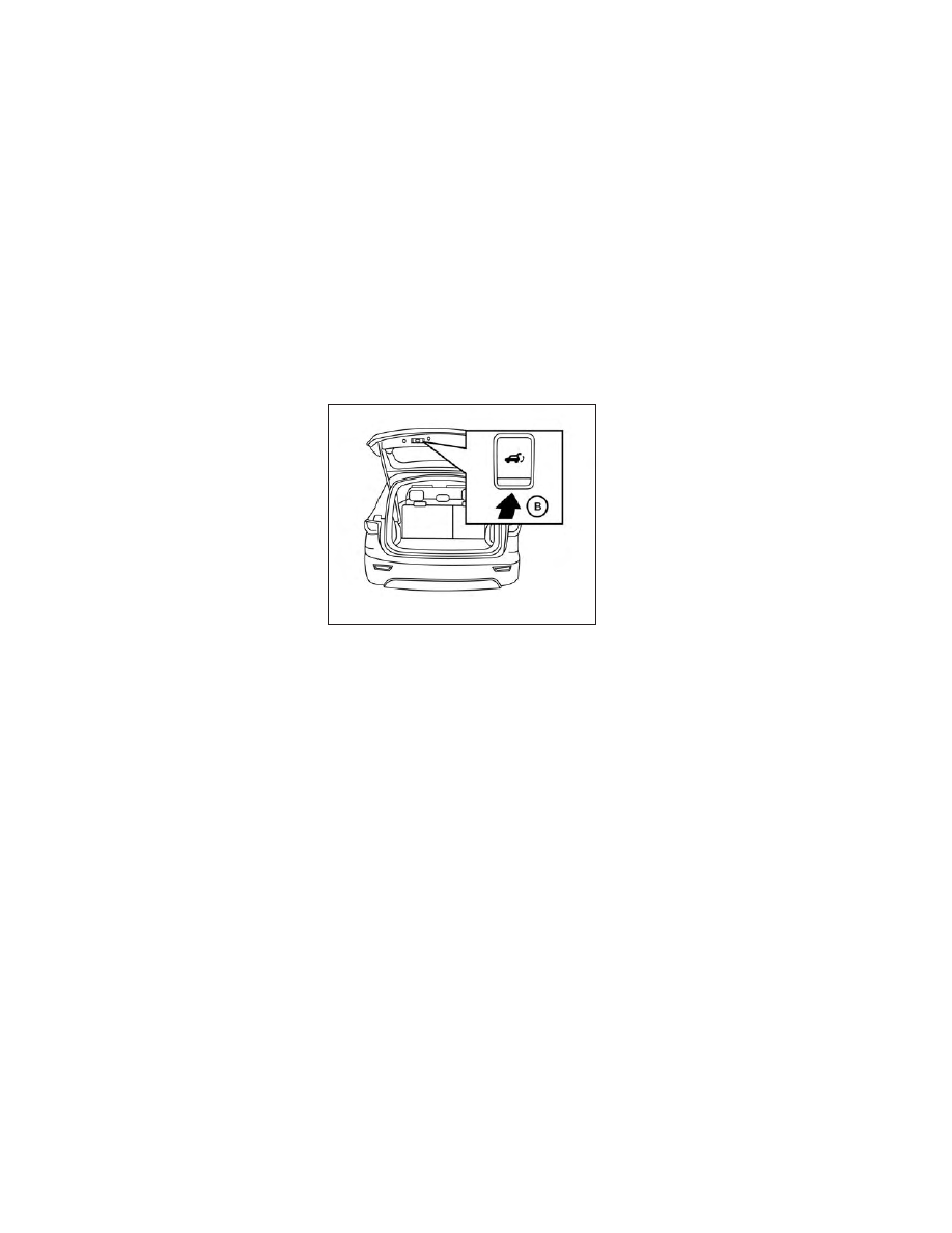
Power Close:
The power liftgate automatically moves
from the fully open position to the second-
ary position. When the liftgate reaches the
secondary position, the cinching motor en-
gages and pulls the liftgate to its primary
latch position. Power close takes approxi-
mately 7 – 10 seconds. The power close
feature can be activated by the switch on
the Intelligent Key, the instrument panel
and the liftgate close switch
O
B
. A chime
sounds to indicate the power close se-
quence has been started.
LPD2295
Liftgate opener switch
LPD2407
Liftgate close switch
Pre-driving checks and adjustments
3-23
-------------------------------------------------------------------------------------------------------------------------------------------------------------
• If the liftgate close switch
O
B
is activated
while the cinching motor is engaged, the
cinching motor will disengage and re-
lease the latch.
• The Intelligent Key button must be held
for 1 second before the liftgate closes.
Reverse:
The power liftgate will stop immediately
during power open or power close if the
Intelligent Key switch, instrument panel
switch, liftgate opener switch
O
A
or liftgate
close switch
O
B
is pushed. The power lift-
gate will reverse direction if the Intelligent
Key switch, instrument panel switch, lift-
gate opener switch
O
A
or liftgate close
switch
O
B
is pushed a second time. A
chime will sound to announce the reversal.
Auto Reverse:
If an obstacle is detected during power
open or power close, a warning chime will
sound and the liftgate will reverse direction
and return to the full open or full close po-
sition. If a second obstacle is detected, the
liftgate motion will stop and the liftgate will
enter manual mode.
A pinch strip is mounted on each side of
the liftgate. If an obstacle is detected by a
pinch strip during power close, the liftgate
will reverse direction and return to the full
open position.
NOTE:
If the pinch strip is damaged or removed,
the
power
close
function
will
not
operate.
WARNING
There are some small distances imme-
diately
before
the
closed
position
which cannot be detected. Make sure
that all passengers have their hands,
etc., inside the vehicle before closing
the liftgate.
Manual Mode:
If power operation is not available, the lift-
gate may be operated manually. Power op-
eration may not be available if multiple ob-
stacles have been detected in a single
power cycle or if battery voltage is low.
If the liftgate opener switch
O
A
is pushed
during power open or close, the power op-
eration will be canceled and the liftgate can
be operated manually.
To open the liftgate manually, push the lift-
gate opener switch
O
A
and lift the liftgate.
To close, lower and push the liftgate down
securely.
LPD2295
3-24
Pre-driving checks and adjustments
-------------------------------------------------------------------------------------------------------------------------------------------------------------
Auto Power Liftgate System Battery
Power Saving Mode:
The vehicle goes into power saving mode
when the liftgate is open for a long time
(approximately 12 hours). This is to prevent
deterioration of the battery. The power
saving mode automatically cuts the power
supply of the power liftgate door.
When the power to the liftgate is cut off, the
manual mode must be performed. After
the manual mode is performed, the power
liftgate function is restored.
NOTE:
When a battery voltage is lower than ap-
proximately 11V, the power liftgate may
not operate after automatic return.
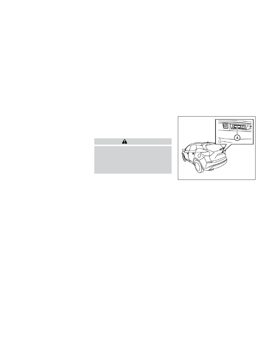
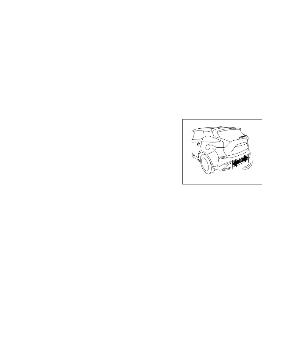
MOTION-ACTIVATED LIFTGATE (if
so equipped)
The liftgate can be operated using a quick
kicking motion under the center of the rear
bumper.
To operate, the Intelligent Key must be
within 47 in (120 cm) of the liftgate.
NOTE:
Tow hitches are available as an acces-
sory for this vehicle. If a tow hitch is in-
stalled, the Motion-Activated Liftgate
electronic control unit (ECU) needs to be
replaced with an ECU programmed with
towing logic for the Motion-Activated
Liftgate to function properly.
Proper operation technique
• While at the rear of the vehicle, begin
making a quick forward kicking motion.
• Raise your foot straight under the center
of the rear bumper then immediately re-
turn your foot to the ground in a continu-
ous motion.
• The kicking motion should be straight,
smooth and consistent.
• After your kick motion is complete, step
back and allow the liftgate to open/close.
LPD2770
Activation zone
Pre-driving checks and adjustments
3-25
-------------------------------------------------------------------------------------------------------------------------------------------------------------
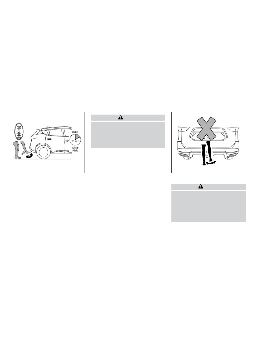
• Three beeps will sound and the liftgate
will begin moving within two seconds af-
ter the kick.
CAUTION
Before performing the kicking motion,
steady your stance to prevent any loss
of balance. Also, while making the kick-
ing motion, take caution around hot ex-
haust system parts. Otherwise, there
may be danger of injury.
WARNING
Prevent
unintentional
liftgate
opening/closing. There may be condi-
tions when opening/closing the lift-
gate is not desired. Keep the Intelligent
Key out of range of the liftgate, (31.5 in
or 80 cm), when washing or working
around the back of the vehicle.
LPD2771
DO: Quick forward kick and return while
the key fob is within range
LPD2764
DO NOT: Swing foot side to side or
pause during kick
3-26
Pre-driving checks and adjustments
-------------------------------------------------------------------------------------------------------------------------------------------------------------
CAUTION
•
Interference or malfunction can be
caused by parking in close proximity
to radio or satellite towers.
•
Intelligent Key interference could be
caused if you have your key fob
stored next to your cell phone or any
RF-enabled smart card. For addi-
tional information, see “NISSAN Intel-
ligent Key® system” (P. 3-7).
LIFTGATE RELEASE
WARNING
•
Always be sure the liftgate has been
closed securely to prevent it from
opening while driving.
•
Do not drive with the liftgate open.
This could allow dangerous exhaust
gases to be drawn into the vehicle.
For additional information, see “Ex-
haust
gas
(carbon
monoxide)”
(P. 5-4).
•
To avoid personal injury, do not at-
tempt to activate the power liftgate
if one or both of the liftgate struts are
removed.
CAUTION
•
If the power liftgate does not stay
open or if the liftgate unexpectedly
closes at any time while a continuous
warning chime sounds, do not oper-
ate the liftgate. There may be a pres-
sure loss in one or both of the liftgate
struts. It is recommended that you
have the liftgate inspected. It is rec-
ommended that you visit a NISSAN
dealer for this service.
•
Do not activate the power liftgate if
one or both of the liftgate struts are
removed. Damage to the liftgate or
power
liftgate
mechanisms
may
occur.
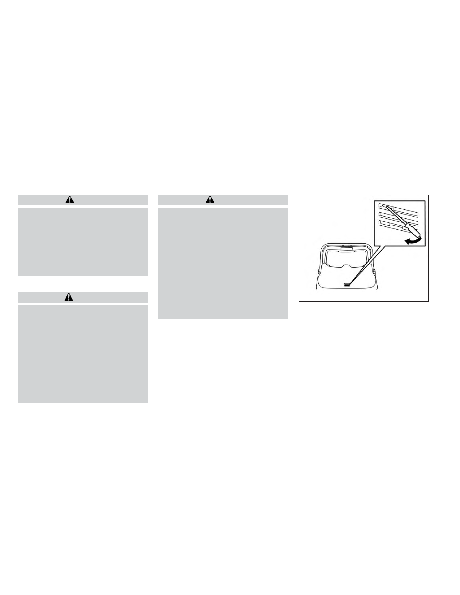
Liftgate release (manual and
power)
The liftgate release mechanism allows the
liftgate to be opened in the event of a dis-
charged battery.
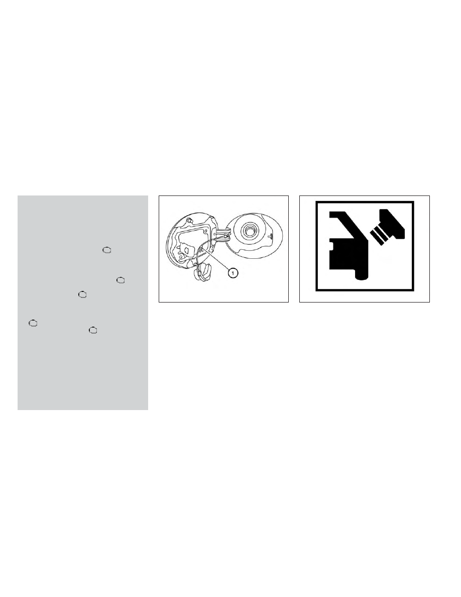
To release the liftgate from the inside of the
vehicle, perform the following operations:
1. Position the rear bench seat forward. For
additional information, see “Rear bench
seat adjustment” (P. 1-6).
2. Insert a suitable tool into the top access
opening at about a 45 degree angle and
rotate to the left until the lock releases.
LPD2319
Pre-driving checks and adjustments
3-27
-------------------------------------------------------------------------------------------------------------------------------------------------------------
3. Push the liftgate up to open.
NOTE:
If you had to open the liftgate using this
procedure, have your vehicle checked as
soon as possible. It is recommended that
you visit a NISSAN dealer for this service.
LIFTGATE POSITION SETTING (if so
equipped)
The liftgate can be set to open to a specific
height (garage mode) by performing the
following:
1. Open the liftgate using the liftgate in-
strument panel switch, liftgate opener
switch or the Intelligent Key button.
2. Pull the liftgate down and move to the
desired height position (the liftgate will
have some resistance when being
manually adjusted).
3. Press and hold the power liftgate close
switch
O
B
located on the liftgate for
more than 3 seconds or until two beeps
are heard.
The liftgate will open to the selected posi-
tion setting. To change the position of the
liftgate, repeat steps 1-3 for setting the po-
sition of the liftgate.
LPD2615
3-28
Pre-driving checks and adjustments
-------------------------------------------------------------------------------------------------------------------------------------------------------------
OPENER OPERATION
The fuel-filler door release is located below
the instrument panel. To open the fuel-filler
door, pull the release. To lock, close the fuel-
filler door securely.
FUEL-FILLER CAP
WARNING
•
Gasoline is extremely flammable and
highly explosive under certain condi-
tions. You could be burned or seri-
ously injured if it is misused or mis-
handled. Always stop the engine and
do not smoke or allow open flames or
sparks
near
the
vehicle
when
refueling.
•
Do not attempt to top off the fuel
tank after the fuel pump nozzle
shuts off automatically. Continued
refueling may cause fuel overflow,
resulting in fuel spray and possibly a
fire.
•
Use only an original equipment type
fuel-filler cap as a replacement. It has
a built-in safety valve needed for
proper operation of the fuel system
and emission control system. An in-
correct cap can result in a serious
malfunction and possible injury. It
could also cause the
Malfunc-
tion Indicator Light (MIL) to come on.
•
Never pour fuel into the throttle body
to attempt to start your vehicle.
•
Do not fill a portable fuel container in
the vehicle or trailer. Static electricity
can cause an explosion of flammable
liquid, vapor or gas in any vehicle or
trailer. To reduce the risk of serious
injury or death when filling portable
fuel containers:
–
Always place the container on the
ground when filling.
–
Do not use electronic devices
when filling.
–
Keep the pump nozzle in contact
with the container while you are
filling it.
–
Use only approved portable fuel
containers for flammable liquid.
CAUTION
•
Do not use a fuel containing more
than 15% ethanol in your vehicle. For
additional information, see “Fuel rec-
ommendation” (P. 10-4).
LPD2022
FUEL-FILLER DOOR
Pre-driving checks and adjustments
3-29
-------------------------------------------------------------------------------------------------------------------------------------------------------------
•
The Loose Fuel Cap warning mes-
sage will appear if the fuel-filler cap
is not properly tightened. It may take
a few driving trips for the message to
be displayed. Failure to tighten the
fuel-filler cap properly after the
Loose Fuel Cap warning message ap-
pears may cause the
Malfunc-
tion
Indicator
Light
(MIL)
to
illuminate.
•
Failure to tighten the fuel-filler cap
properly may cause the
Mal-
function Indicator Light (MIL) to illu-
minate. If the
light illuminates
because the fuel-filler cap is loose or
missing, tighten or install the cap and
continue to drive the vehicle. The
light should turn off after a few
driving trips. If the
light does not
turn off after a few driving trips, have
the vehicle inspected. It is recom-
mended that you visit a NISSAN
dealer for this service.
•
For additional information, see “Mal-
function
Indicator
Light
(MIL)”
(P. 2-13).
•
If fuel is spilled on the vehicle body,
flush it away with water to avoid
paint damage.
To remove the fuel-filler cap:
1. Turn the fuel-filler cap counterclockwise
to remove.
2. Put the fuel-filler cap on the cap holder
O
1
while refueling.
To install the fuel-filler cap:
1. Insert the fuel-filler cap straight into the
fuel-filler tube.
2. Turn the fuel-filler cap clockwise until it
clicks.
Loose Fuel Cap warning message
The Loose Fuel Cap warning message ap-
pears in the vehicle information display
when the fuel-filler cap is not tightened
correctly after the vehicle has been refu-
eled. It may take a few driving trips for the
message to be displayed. To turn off the
warning message, perform the following:
1. Remove and install the fuel-filler cap as
soon as possible. For additional informa-
tion, see “Fuel-filler cap” (P. 3-29).
2. Tighten the fuel-filler cap until it clicks.
LPD2288
LPD3029
3-30
Pre-driving checks and adjustments
-------------------------------------------------------------------------------------------------------------------------------------------------------------
3. Press the OK button on the steering
wheel for about one second to turn off
the Loose Fuel Cap warning message
after tightening the fuel-filler cap.
WARNING
•
Do not adjust the steering wheel
while driving. You could lose control
of
your
vehicle
and
cause
an
accident.
•
Do not adjust the steering wheel any
closer to you than is necessary for
proper steering operation and com-
fort. The driver's air bag inflates with
great force. If you are unrestrained,
leaning forward, sitting sideways or
out of position in any way, you are at
greater risk of injury or death in a
crash. You may also receive serious
or fatal injuries from the air bag if you
are up against it when it inflates. Al-
ways sit back against the seatback
and as far away as practical from the
steering wheel. Always use the seat
belts.
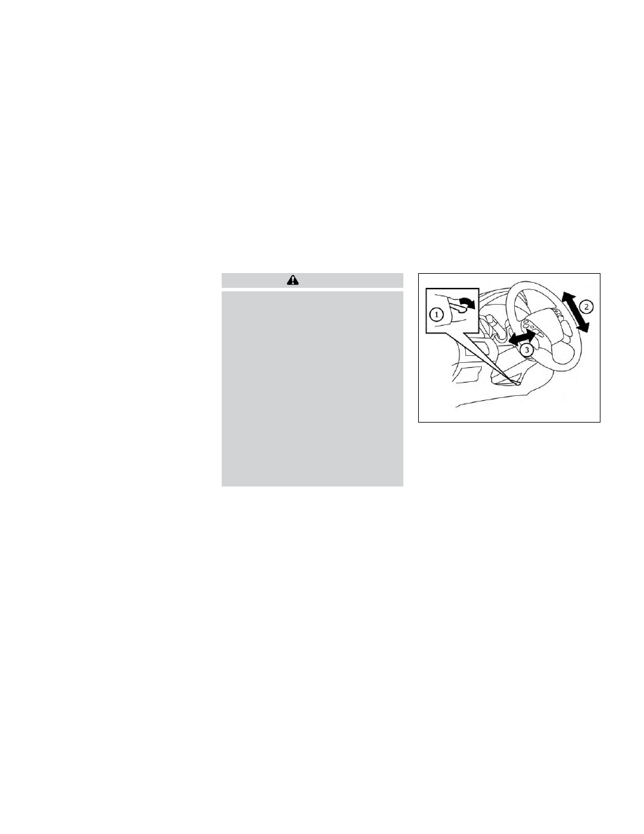
MANUAL OPERATION (if so
equipped)
Tilt and telescopic operation
Push the lock lever
O
1
down:
• Adjust the steering wheel up or down in
direction
O
2
to the desired position.
• Adjust the steering wheel forward or
backward in direction
O
3
to the desired
position.
Pull the lock lever
O
1
up firmly to lock the
steering wheel in place.
LPD2741
STEERING WHEEL
Pre-driving checks and adjustments
3-31
-------------------------------------------------------------------------------------------------------------------------------------------------------------
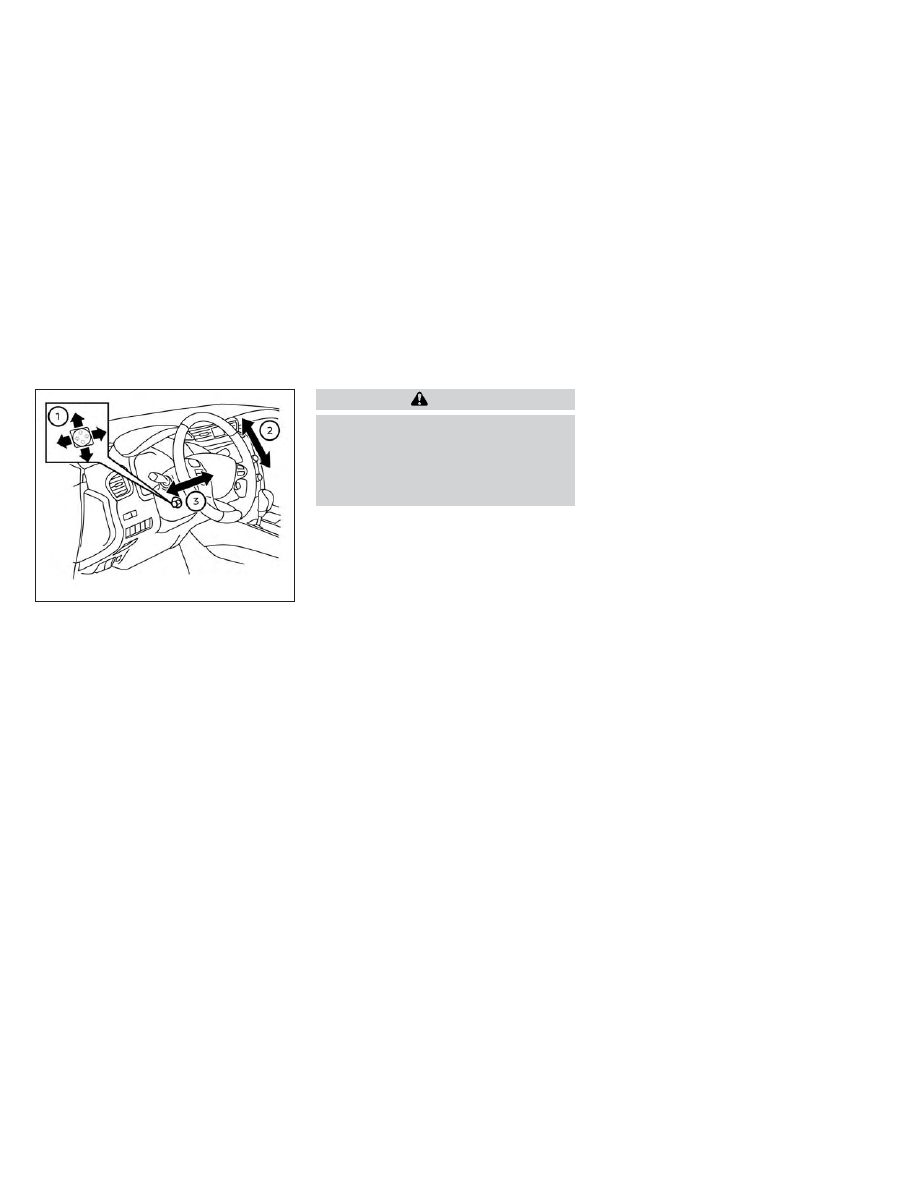
AUTOMATIC OPERATION (if so
equipped)
Tilt and telescopic operation
To adjust the steering wheel move the
switch
O
1
in the following directions:
• Adjust the steering wheel up or down in
direction
O
2
to the desired tilt position.
• Adjust the steering wheel forward or
backward in direction
O
3
to the desired
telescopic position.
CAUTION
For vehicles with memory seat: Failure
to reset the tilt and telescoping func-
tions of the steering wheel, after the
vehicle’s battery has been discharged,
may prevent the steering wheel posi-
tion from being adjusted.
For vehicles with memory seat: Both the tilt
and telescopic steering operation must be
reset after the vehicle’s battery has been
discharged in order to prevent the tilt and
telescopic operation from locking in one
position. When the battery has been re-
charged or replaced, perform the following:
• For tilt operation: Adjust the switch
O
1
so
the steering wheel moves to the highest
position
O
2
that can be reached.
• For
telescopic
operation: Adjust
the
switch
O
1
so the steering wheel moves to
the most forward and backward position
O
3
that can be reached.
Performing these operations resets the
range of the steering wheel’s tilt and tele-
scopic function.
Entry/Exit function (if so
equipped)
The memory seat will make the steering
wheel move up automatically when the
driver's door is opened and the ignition
switch is in the LOCK position. This lets the
driver get into and out of the seat more
easily. The steering wheel moves back into
position when the driver's door is closed
and the ignition switch is pushed.
For additional information, see “Memory
seat” (P. 3-37).
LPD3132
3-32
Pre-driving checks and adjustments
-------------------------------------------------------------------------------------------------------------------------------------------------------------
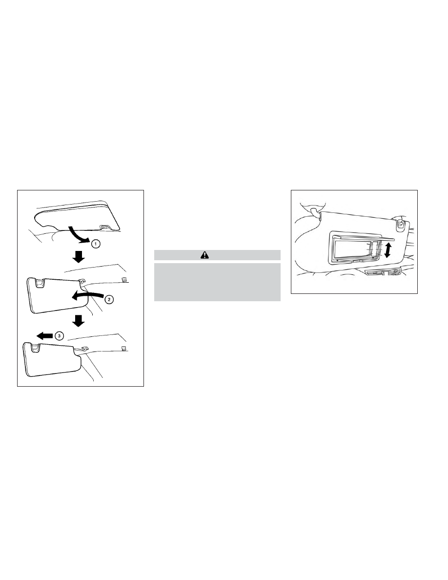
1. To block glare from the front, swing
down
O
1
the main sun visor.
2. To block glare from the side, remove the
main sun visor from the center mount
and swing the visor to the side
O
2
.
3. To extend
O
3
the sun visor, slide in or out
as needed.
CAUTION
•
Do not store the sun visor before re-
turning the extension to its original
position.
•
Do not pull the extension sun visor
forcedly downward.
VANITY MIRRORS
To access the vanity mirror, pull the sun
visor down and flip open the mirror cover.
The vanity mirror will illuminate when the
mirror cover is open.
WPD0344
LPD2703
SUN VISORS
Pre-driving checks and adjustments
3-33
-------------------------------------------------------------------------------------------------------------------------------------------------------------
CARD HOLDER
To use the card holder, slide card into the
clip. Do not view information while operat-
ing the vehicle.
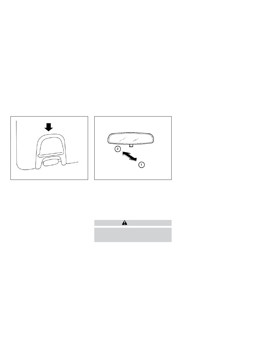
MANUAL ANTI-GLARE REARVIEW
MIRROR (if so equipped)
Use the night position
O
1
to reduce glare
from the headlights of vehicles behind you
at night.
Use the day position
O
2
when driving in
daylight hours.
WARNING
Use the night position only when nec-
essary, because it reduces rear view
clarity.
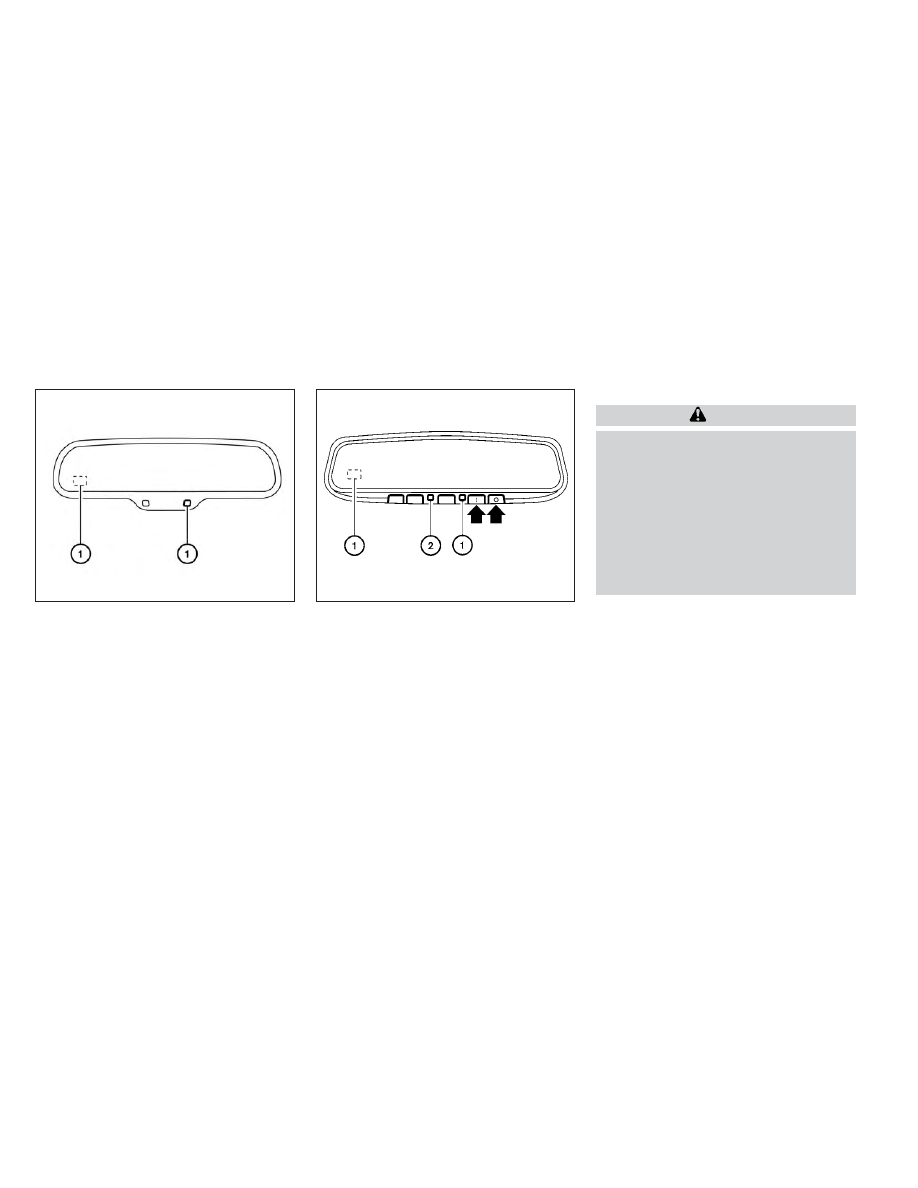
AUTOMATIC ANTI-GLARE
REARVIEW MIRROR (if so equipped)
The inside mirror is designed so that it au-
tomatically dims during nighttime condi-
tions and according to the intensity of the
headlights of the vehicle following you. The
automatic anti-glare feature is activated
when the ignition switch is in the ON
position.
The indicator light
O
2
will illuminate when
the
automatic
anti-glare
feature
is
operating.
NOTE:
Do not hang any objects over the sen-
sors
O
1
or apply glass cleaner to the sen-
sors. Doing so will reduce the sensitivity
of the sensors, resulting in improper
operation.
LPD2340
Driver’s and passenger’s side
WPD0126
MIRRORS
3-34
Pre-driving checks and adjustments
-------------------------------------------------------------------------------------------------------------------------------------------------------------
Type A (if so equipped)
The inside mirror is designed so that it au-
tomatically dims during night time condi-
tions and according to the intensity of the
headlights of the vehicle following you. The
automatic anti-glare feature is activated
when the ignition switch is in the ON
position.
Type B (if so equipped)
The indicator light
O
2
will illuminate when
the automatic anti-glare feature is operat-
ing.
• To turn off the automatic anti-glare fea-
ture, press the
O
button. The indicator
light will turn off.
• To turn on the automatic anti-glare fea-
ture, press the
|
button again. The in-
dicator light will turn on.
For additional information on HomeLink®
Universal
Transceiver
operation,
see
“HomeLink® Universal Transceiver” (P. 2-68).
OUTSIDE MIRRORS
WARNING
•
Do not adjust the mirrors while driv-
ing. You could lose control of your ve-
hicle and cause an accident.
•
Objects viewed in the outside mirror
on the passenger side are closer than
they appear. Be careful when moving
to the right. Using only this mirror
could cause an accident. Use the in-
side mirror or glance over your
shoulder to properly judge distances
to other objects.
LPD2418
LPD0469
Pre-driving checks and adjustments
3-35
-------------------------------------------------------------------------------------------------------------------------------------------------------------
Нет комментариевНе стесняйтесь поделиться с нами вашим ценным мнением.
Текст