Nissan Murano. Manual — part 83

AV-110
< DTC/CIRCUIT DIAGNOSIS >
[BASE AUDIO WITH COLOR DISPLAY]
U1216 AV CONTROL UNIT
U1216 AV CONTROL UNIT
DTC Logic
INFOID:0000000009721623
DTC
Display contents of
CONSULT
DTC detection condition
Possible malfunction factor
U1216
CAN CONT
[U1216]
AV control unit malfunction is detected.
Replace the AV control unit if the mal-
function occurs constantly.
Refer to
AV
U1232 STEERING ANGLE SENSOR
AV-111
< DTC/CIRCUIT DIAGNOSIS >
[BASE AUDIO WITH COLOR DISPLAY]
C
D
E
F
G
H
I
J
K
L
M
B
A
O
P
U1232 STEERING ANGLE SENSOR
DTC Logic
INFOID:0000000009721624
Diagnosis Procedure
INFOID:0000000009721625
1.
ADJUST THE PREDICTIVE COURSE LINE CENTER POSITION OF THE STEERING ANGLE SENSOR
When U1232 is detected, adjust the predictive course line center position of the steering angle sensor.
>> Adjusts the steering angle sensor neutral position on ABS actuator and electrical unit (control unit)
side. Refer to
BRC-9, "ADJUSTMENT OF STEERING ANGLE SENSOR NEUTRAL POSITION :
.
DTC
Display contents of
CONSULT
DTC detection condition
Possible malfunction factor
U1232
ST ANGLE SEN CALIB
[1232]
Predictive course line center position adjustment of the
steering angle sensor is incomplete.
Adjust the predictive course line cen-
ter position of the steering angle sen-
sor.
AV-112
< DTC/CIRCUIT DIAGNOSIS >
[BASE AUDIO WITH COLOR DISPLAY]
U1243 DISPLAY UNIT
U1243 DISPLAY UNIT
DTC Logic
INFOID:0000000009721626
Diagnosis Procedure
INFOID:0000000009721627
1.
CHECK DISPLAY UNIT POWER SUPPLY AND GROUND CIRCUIT
Check display unit power supply and ground circuit. Refer to
AV-118, "DISPLAY UNIT : Diagnosis Procedure"
.
Is the inspection result normal?
YES
>> GO TO 2.
NO
>> Repair malfunctioning parts.
2.
CHECK CONTINUITY COMMUNICATION CIRCUIT
1.
Turn ignition switch OFF.
2.
Disconnect display unit connector and AV control unit connector.
3.
Check continuity between display unit harness connector and AV control unit harness connector.
4.
Check continuity between display unit harness connector and ground.
Is the inspection result normal?
YES
>> GO TO 3.
NO
>> Repair harness or connector.
3.
CHECK COMMUNICATION SIGNAL
1.
Connect display unit connector and AV control unit connector.
2.
Turn ignition switch ON.
3.
Check signal between display unit harness connector and ground.
DTC
Display contents of
CONSULT
DTC detection condition
Possible malfunction factor
U1243
FRONT DISP CONN
[U1243]
When either one of the following items are detected:
• display unit power supply and ground circuits are mal-
functioning.
• serial communication circuits between display unit and
AV control unit are malfunctioning.
• Display unit power supply and
ground circuits.
• Serial communication circuits be-
tween display unit and AV control
unit.
Display unit
AV control unit
Continuity
Connector
Terminals
Connector
Terminals
M194
11
M172
51
Existed
22
39
Display unit
Ground
Continuity
Connector
Terminals
M194
11
Not existed
12
AV
U1243 DISPLAY UNIT
AV-113
< DTC/CIRCUIT DIAGNOSIS >
[BASE AUDIO WITH COLOR DISPLAY]
C
D
E
F
G
H
I
J
K
L
M
B
A
O
P
Is the inspection result normal?
YES
>> GO TO 4.
NO
>> Replace AV control unit. Refer to
4.
CHECK COMMUNICATION SIGNAL
Check signal between display unit harness connector and ground.
Is the inspection result normal?
YES
>> INSPECTION END
NO
>> Replace display unit. Refer to
.
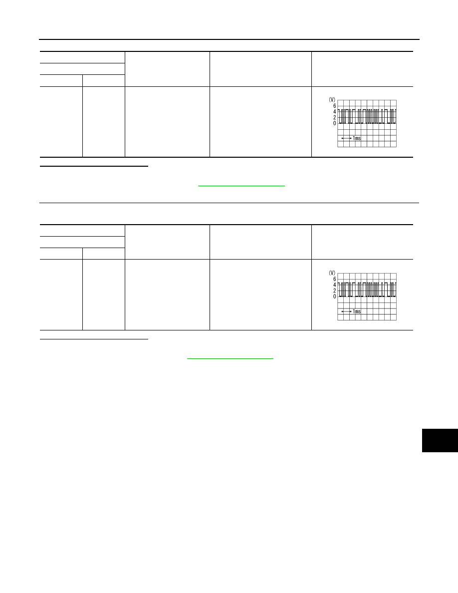
(+)
(
−
)
Condition
Reference value
Display unit
Connector
Terminal
M194
11
Ground
When adjusting display bright-
ness.
PKIB5039J
(+)
(
−
)
Condition
Reference value
Display unit
Connector
Terminal
M194
22
Ground
When adjusting display bright-
ness.
PKIB5039J
Нет комментариевНе стесняйтесь поделиться с нами вашим ценным мнением.
Текст