Nissan Murano. Manual — part 100
AV-178
< SYSTEM DESCRIPTION >
[BOSE AUDIO WITHOUT NAVIGATION]
DIAGNOSIS SYSTEM (AV CONTROL UNIT)
DIAGNOSIS SYSTEM (AV CONTROL UNIT)
Description
INFOID:0000000009721719
• The AV control unit diagnosis function starts up with multifunction switch operation and the AV control unit
performs a diagnosis for each unit in the system during the on board diagnosis.
• Perform a CONSULT diagnosis if the on board diagnosis does not start, e.g., the screen does not display
anything, the multifunction switch does not function, etc.
On Board Diagnosis Function
INFOID:0000000009721720
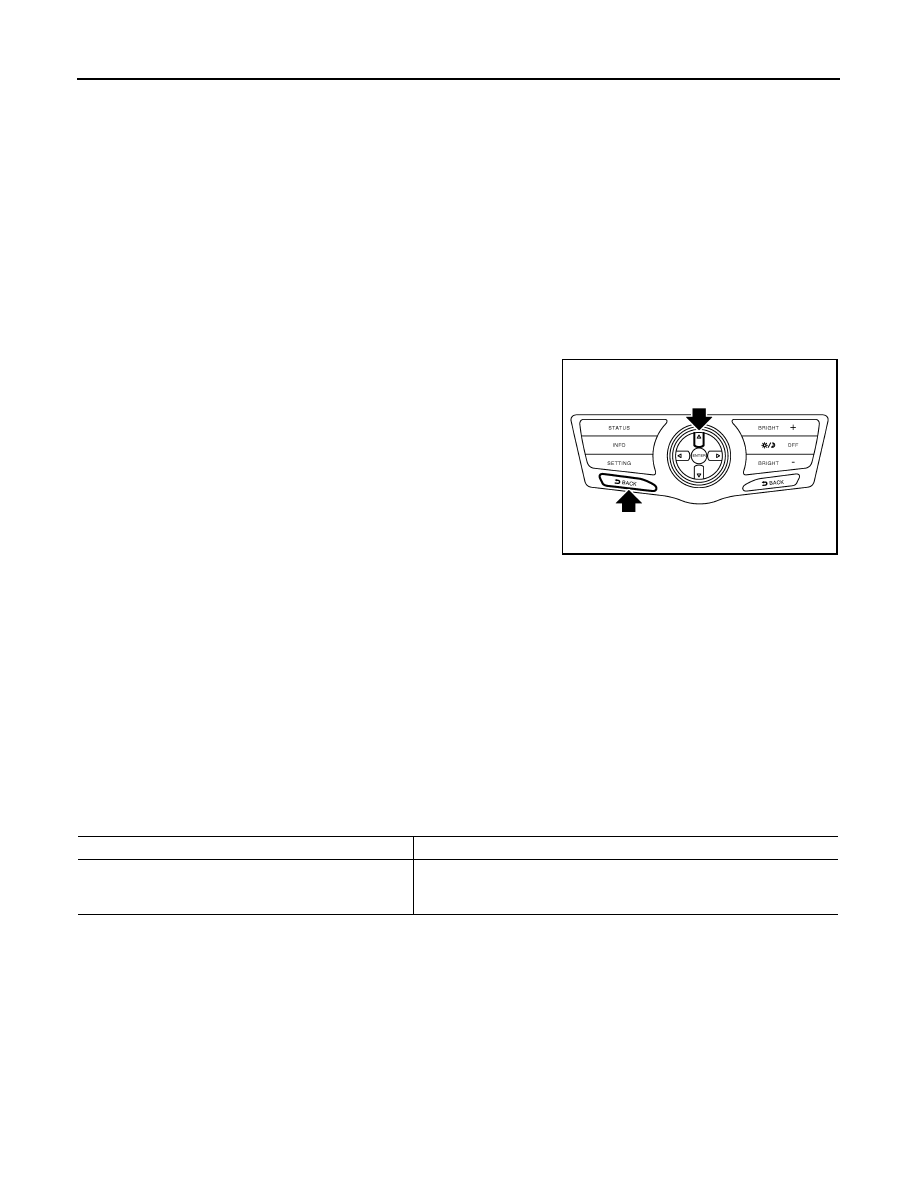
MULTIFUNCTION SWITCH AND PRESET SWITCH SELF-DIAGNOSIS FUNCTION
The ON/OFF operation (continuity) of each switch in the multifunction switch and preset switch can be
checked.
Self-diagnosis Mode
• Press the “BACK” switch and the “UP” switch of the 8-direction
switches within 10 seconds after turning the ignition switch from
OFF to ACC and hold them for 3 seconds or more. Then the
buzzer sounds, all indicators of the preset switch illuminate, and
the self-diagnosis mode starts.
• The continuity of each switch at the ON position can be checked
by pressing the switch. The buzzer sounds if the switch is normal.
NOTE:
The hazard switch and disk eject switch cannot be checked.
Finishing Self-diagnosis Mode
Self-diagnosis mode is canceled when turning the ignition switch OFF.
ON BOARD DIAGNOSIS
Description
• The trouble diagnosis function has a self-diagnosis mode for conducting trouble diagnosis automatically and
a confirmation/adjustment mode for operating manually.
• Self-diagnosis mode performs the AV control unit diagnosis and the connection diagnosis between each of
the units that make up the system, and it indicates the results to the display.
• The confirmation/adjustment mode allows the technician to check, modify or adjust the vehicle signals and
set values, as well as to monitor the system error records and system communication status. The checking,
modifying or adjusting generally require human intervention and judgment (the system cannot make judg-
ment automatically).
On Board Diagnosis Item
JSNIA1072GB
Mode
Description
Self Diagnosis
• AV control unit diagnosis.
• Diagnoses the connections across system components, between AV
control unit and each unit.
AV
DIAGNOSIS SYSTEM (AV CONTROL UNIT)
AV-179
< SYSTEM DESCRIPTION >
[BOSE AUDIO WITHOUT NAVIGATION]
C
D
E
F
G
H
I
J
K
L
M
B
A
O
P
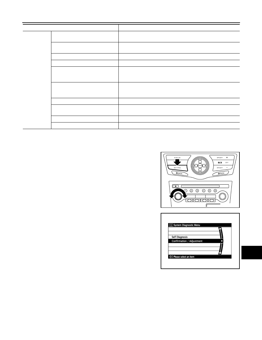
STARTING PROCEDURE
1.
Start the engine.
2.
Turn the audio system OFF.
3.
While pressing the “SETTING” button, turn the volume control
dial clockwise or counterclockwise for 40 clicks or more. (When
the self-diagnosis mode is started, the trouble diagnosis initial
screen is displayed.)
• Shifting from current screen to previous screen is performed
by pressing “BACK” button.
4.
Items of “Self Diagnosis” and “Confirmation/Adjustment” can be
selected on the trouble diagnosis initial screen.
SELF-DIAGNOSIS MODE
1.
Start the self-diagnosis function and select “Self Diagnosis”.
-
Self-diagnosis subdivision screen is displayed, and the self-diagnosis mode starts.
-
The bar graph visible on the center of the self-diagnosis subdivision screen indicates progress of the trou-
ble diagnosis.
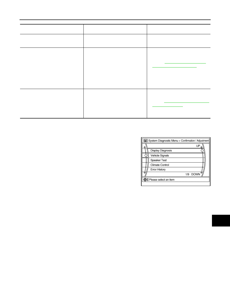
Confirmation/
Adjustment
Display Diagnosis
The following check functions are available: color tone check by color bar
display and white display, light and shade check by gray scale display.
Vehicle Signals
Diagnosis of signals can be performed for vehicle speed, parking brake,
lights, ignition and reverse.
Speaker Test
The connection of a speaker can be confirmed by test tone.
Climate Control
Start auto air conditioner system self-diagnosis.
Error History
The system malfunction and the frequency when occurring in the past are
displayed. When the malfunctioning item is selected, the time and place
that the selected malfunction last occurred are displayed.
Camera Cont.
• Guiding line position that overlaps rear view camera image can be ad-
justed.
• Configuration stored in the AV control unit can be checked.
Vehicle CAN Diagnosis
The transmitting/receiving of CAN communication can be monitored.
AV COMM Diagnosis
The communication condition of each unit of Multi AV system can be mon-
itored.
Delete Unit Connection Log
Erase the connection history of unit and error history.
Initialize Settings
Initializes the AV control unit memory.
Mode
Description
JSNIA1073GB
SKIB3961E
AV-180
< SYSTEM DESCRIPTION >
[BOSE AUDIO WITHOUT NAVIGATION]
DIAGNOSIS SYSTEM (AV CONTROL UNIT)
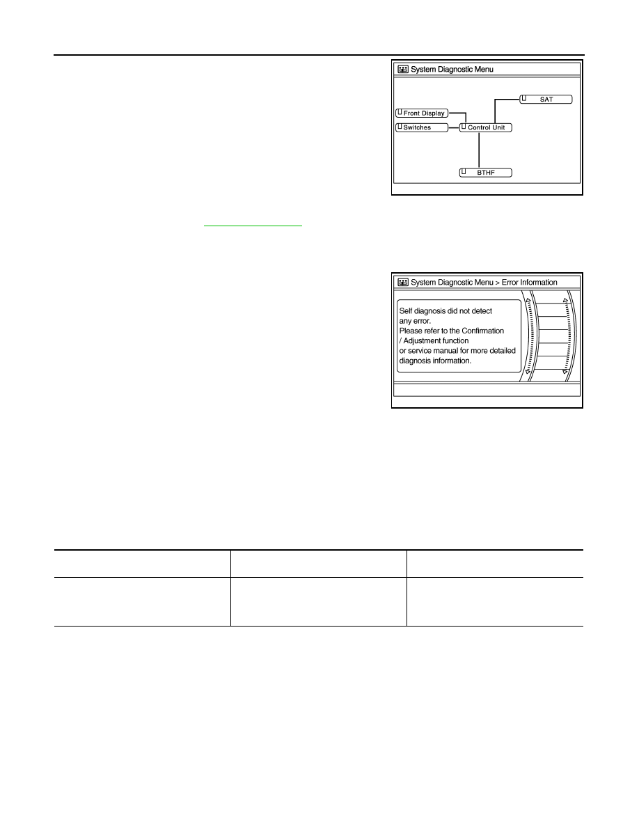
2.
Diagnosis results are displayed after the self-diagnosis is com-
pleted. The unit names and the connection lines are color-coded
according to the diagnostic results.
NOTE:
Control unit (AV control unit) and is displayed in red.
• Replace AV control unit if “Self-Diagnosis did not run because of a control unit malfunction” is indicated. The symptom is AV con-
trol unit internal error. Refer to
• If multiple errors occur at the same time for a single unit, the screen switch colors are determined according to the following order
of priority: red > gray.
-
The comments of the self-diagnosis results can be viewed with a
component in the diagnosis result screen.
Detection Range of Self-diagnosis Mode
• The self-diagnosis mode allows the technician to diagnose the connection in the communication line
between AV control unit and each unit and the internal operation of the AV control unit.
• Because the start condition of diagnosis function is a switch operation, the on board diagnosis function can-
not be started up if any malfunction is detected in the communication circuit between AV control unit and
multifunction switch.
SELF-DIAGNOSIS RESULTS
Check the applicable display at the following table, and then repair the malfunctioning parts.
Only Unit Part Is Displayed In Red.
A Connecting Cable Between Units Is Displayed In Yellow.
Diagnosis results
Unit
Connec-
tion line
Normal
Green
Green
Connection malfunction
Gray
Yellow
Unit malfunction
Note
Red
Green
JSNIA2528ZZ
JSNIA0141GB
Screen switch
Description
Possible malfunction location / Action to
take
Control unit
Malfunction is detected in AV control unit
power supply and ground circuits.
Check AV control unit power supply and
ground circuits. When detecting no mal-
function in those components, replace AV
control unit.
AV
DIAGNOSIS SYSTEM (AV CONTROL UNIT)
AV-181
< SYSTEM DESCRIPTION >
[BOSE AUDIO WITHOUT NAVIGATION]
C
D
E
F
G
H
I
J
K
L
M
B
A
O
P
CONFIRMATION/ADJUSTMENT MODE
1.
Start the diagnosis function and select “Confirmation/Adjustment”. The confirmation/adjustment mode
indicates where each item can be checked or adjusted.
2.
Select each switch on the “Confirmation/Adjustment Mode”
screen to display the relevant trouble diagnosis screen. Press
the “BACK” switch to return to the initial Confirmation/Adjust-
ment Mode screen.
Area with yellow connection lines
Description
Possible malfunction location / Action to
take
Control unit
⇔
Front Display
Malfunction is detected in serial communi-
cation circuits between AV control unit and
display unit.
Serial communication circuits between AV
control unit and display unit.
Control unit
⇔
SAT
When either one of the following items is
detected:
• satellite radio tuner power supply and
ground circuit are malfunctioning.
• communication circuits between AV con-
trol unit and satellite radio tuner are mal-
functioning.
• request signal circuit between AV control
unit and satellite radio tuner are malfunc-
tioning.
• Satellite radio tuner power supply and
ground circuit.
Refer to
• Communication circuit between AV con-
trol unit and satellite radio tuner.
• Request signal circuit between AV con-
trol unit and satellite radio tuner.
Control unit
⇔
BTHF
When either one of the following items is
detected:
• TEL adapter unit power supply and
ground circuits are malfunctioning.
• AV communication circuits between AV
control unit and TEL adapter unit are
malfunctioning.
• TEL adapter unit power supply and
ground circuits.
Refer to
.
• AV communication circuits between AV
control unit and TEL adapter unit.
JSNIA0147GB
Нет комментариевНе стесняйтесь поделиться с нами вашим ценным мнением.
Текст