Nissan Murano. Manual — part 294
DAS-66
< DTC/CIRCUIT DIAGNOSIS >
[LDW]
U111A REAR CAMERA IMAGE SIGNAL CIRCUIT
U111A REAR CAMERA IMAGE SIGNAL CIRCUIT
DTC Logic
INFOID:0000000009723255
DTC DETECTION LOGIC
DTC CONFIRMATION PROCEDURE
1.
PERFORM DTC CONFIRMATION PROCEDURE
1.
Turn the ignition switch ON.
2.
Shift the selector lever to “R” position.
3.
Perform “All DTC Reading” with CONSULT.
4.
Check if the “U111A” is detected as the current malfunction in “Self Diagnostic Result” of “AVM”.
Is “U111A” detected as the current malfunction?
YES
>> Refer to
.
NO
>> Refer to
GI-44, "Intermittent Incident"
.
Diagnosis Procedure
INFOID:0000000009723256
1.
CHECK CONTINUITY REAR VIEW CAMERA POWER SUPPLY AND GROUND CIRCUIT
1.
Turn ignition switch OFF.
2.
Disconnect camera control unit connector and rear view camera connector.
3.
Check continuity between camera control unit harness connector and rear view camera harness connec-
tor.
4.
Check continuity between camera control unit harness connector and ground.
Is inspection result normal?
YES
>> GO TO 2.
NO
>> Repair harness or connector.
2.
CHECK VOLTAGE REAR VIEW CAMERA POWER SUPPLY
1.
Connect camera control unit connector and rear view camera connector.
2.
Turn ignition switch ON.
3.
Check voltage between camera control unit harness connector and ground.
DTC
Trouble diagnosis name
DTC detecting condition
Possible causes
U111A
REAR CAMERA IMAGE
SIGNAL
Camera image signal circuit is open or shorted.
• Camera image signal circuit be-
tween rear view camera and cam-
era control unit
• Camera control unit
• Rear view camera
Camera control unit
Rear view camera
Continuity
Connector
Terminals
Connector
Terminals
B93
50
D168
8
Existed
52
7
Camera control unit
Ground
Continuity
Connector
Terminal
B93
50
Not existed
DAS
U111A REAR CAMERA IMAGE SIGNAL CIRCUIT
DAS-67
< DTC/CIRCUIT DIAGNOSIS >
[LDW]
C
D
E
F
G
H
I
J
K
L
M
B
N
P
A
Is inspection result normal?
YES
>> GO TO 3.
NO
>> Replace camera control unit. Refer to
DAS-94, "Removal and Installation"
.
3.
CHECK CONTINUITY CAMERA IMAGE SIGNAL CIRCUIT
1.
Turn ignition switch OFF.
2.
Disconnect camera control unit connector and rear view camera connector.
3.
Check continuity between camera control unit harness connector and rear view camera harness connec-
tor.
4.
Check continuity between camera control unit harness connector and ground.
Is inspection result normal?
YES
>> GO TO 4.
NO
>> Repair harness or connector.
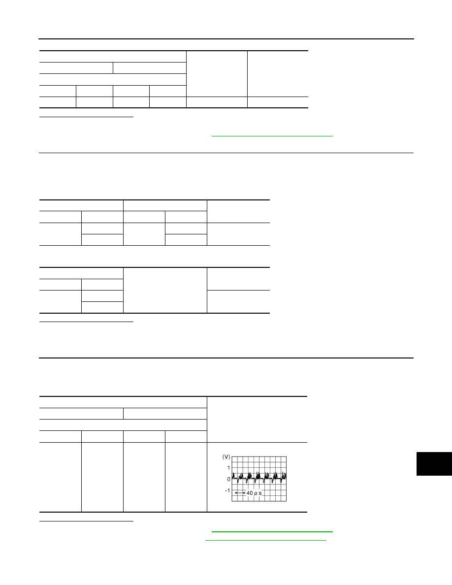
4.
CHECK CAMERA IMAGE SIGNAL
1.
Connect camera control unit connector and rear view camera connector.
2.
Turn ignition switch ON.
3.
Check signal between camera control unit harness connector.
Is inspection result normal?
YES
>> Replace camera control unit. Refer to
DAS-94, "Removal and Installation"
.
NO
>> Replace rear view camera. Refer to
DAS-95, "Removal and Installation"
.
Terminal
Standard voltage
Reference voltage
(Approx.)
(+)
(
−
)
Camera control unit
Connector
Terminal
Connector
Terminal
B93
50
B93
52
5.0 - 9.0 V
6.0 V
Camera control unit
Rear view camera
Continuity
Connector
Terminals
Connector
Terminals
B93
53
D168
5
Existed
54
1
Camera control unit
Ground
Continuity
Connector
Terminals
B93
53
Not existed
54
Terminal
Reference value
(+)
(
−
)
Camera control unit
Connector
Terminal
Connector
Terminal
B93
53
B93
54
JSNIA0834GB

DAS-68
< DTC/CIRCUIT DIAGNOSIS >
[LDW]
U1232 STEERING ANGLE SENSOR
U1232 STEERING ANGLE SENSOR
DTC Logic
INFOID:0000000009723257
Diagnosis Procedure
INFOID:0000000009723258
1.
REGISTER THE NEUTRAL POSITION OF THE STEERING ANGLE SENSOR
1.
Turn the ignition switch ON.
2.
Perform registration of the neutral position of the steering angle sensor. Refer to
OF STEERING ANGLE SENSOR NEUTRAL POSITION : Special Repair Requirement"
3.
Check “Self Diagnostic Result” of “AVM” with CONSULT.
Is “U1232” detected as the current malfunction?
YES
>> GO TO 2.
NO
>> INSPECTION END
2.
CHECK STEERING ANGLE SENSOR
Check steering angle sensor.
Is the inspection result normal?
YES
>> Replace the camera control unit. Refer to
DAS-94, "Removal and Installation"
.
NO
>> Repair or replace malfunctioning parts.
DTC
Trouble diagnosis name
DTC detecting condition
Possible causes
U1232
ST ANGLE SEN CALIB
The neutral position registration of the steering angle sen-
sor can not finish.
• Steering angle sensor
• Camera control unit

DAS
U1305 CONFIG UNFINISH
DAS-69
< DTC/CIRCUIT DIAGNOSIS >
[LDW]
C
D
E
F
G
H
I
J
K
L
M
B
N
P
A
U1305 CONFIG UNFINISH
DTC Logic
INFOID:0000000009723259
NOTE:
Current malfunction is displayed only and is not saved.
Diagnosis Procedure
INFOID:0000000009723260
1.
PERFORM CONFIGURATION OF CAMERA CONTROL UNIT
Perform configuration of camera control unit when DTC U1305 is detected.
>> Perform configuration of camera control unit. Refer to
DTC
Trouble diagnosis name
DTC detecting condition
Possible causes
U1305
CONFIG UNFINISH
The vehicle specifications of camera control unit is incom-
plete.
Vehicle specifications for camera
control unit is incomplete
Нет комментариевНе стесняйтесь поделиться с нами вашим ценным мнением.
Текст