Nissan Murano. Manual — part 104
AV-194
< ECU DIAGNOSIS INFORMATION >
[BOSE AUDIO WITHOUT NAVIGATION]
AV CONTROL UNIT
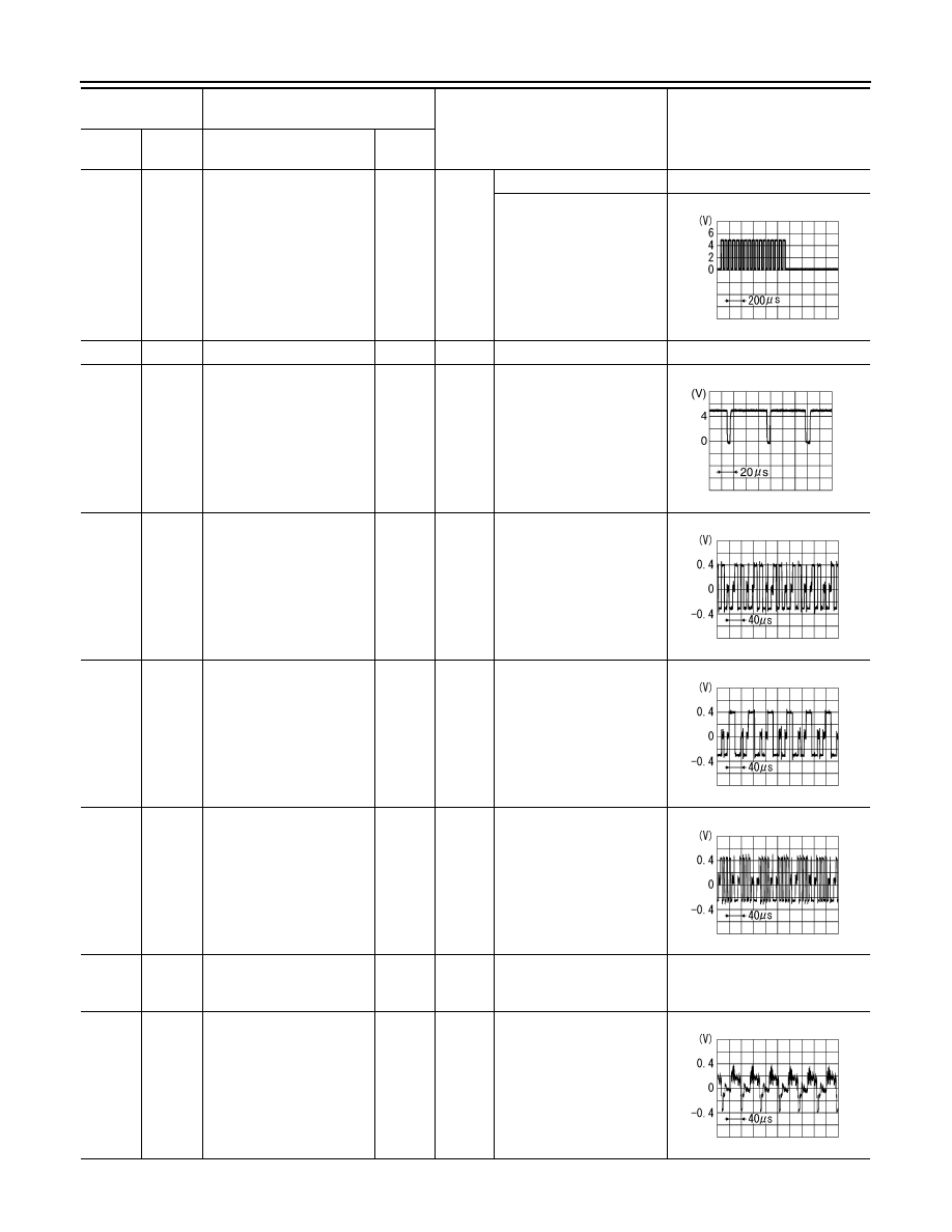
40
(W)
Ground
RGB area (YS) signal
Output
Ignition
switch
ON
At RGB image is displayed.
5.0 V
At AUX image is displayed.
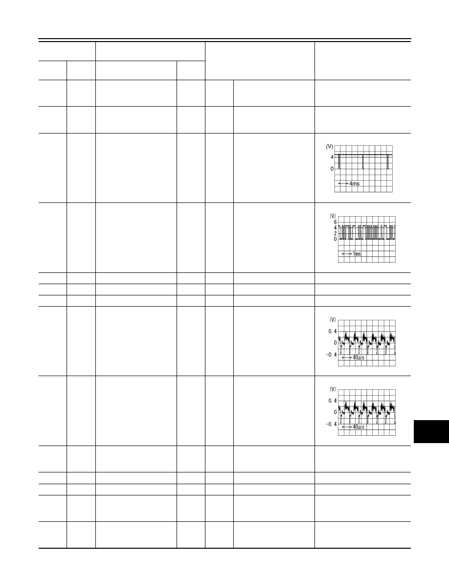
41
—
Shield
—
—
—
—
42
(B)
Ground
RGB synchronizing signal
Output
Ignition
switch
ON
—
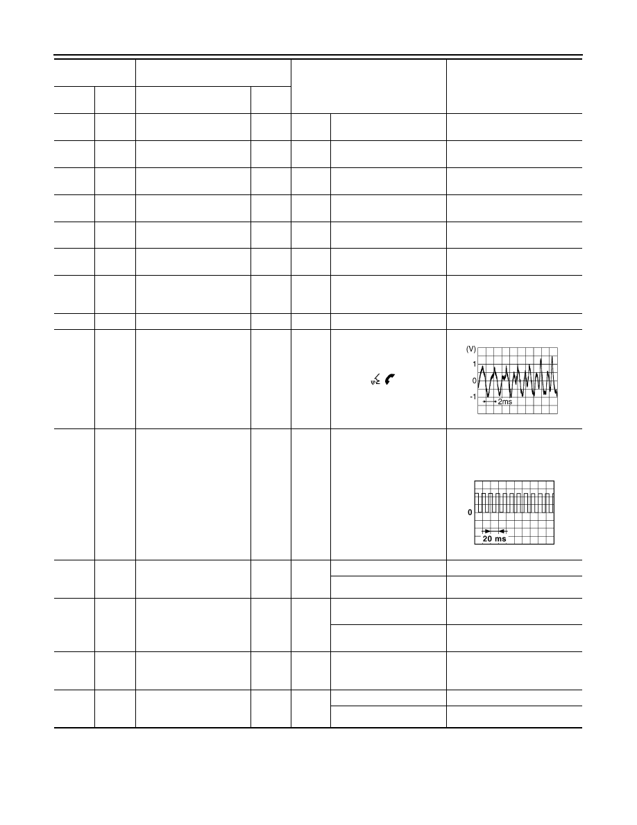
43
(G)
Ground
RGB signal (R: red)
Output
Ignition
switch
ON
Start Confirmation/Adjust-
ment mode, and then dis-
play color bar by selecting
“Color Spectrum Bar” on
Display Diagnosis screen.
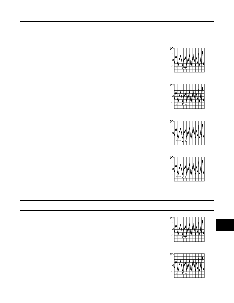
44
(L)
Ground
RGB signal (G: green)
Output
Ignition
switch
ON
Start Confirmation/Adjust-
ment mode, and then dis-
play color bar by selecting
“Color Spectrum Bar” on
Display Diagnosis screen.
45
(Y)
Ground
RGB signal (B: blue)
Output
Ignition
switch
ON
Start Confirmation/Adjust-
ment mode, and then dis-
play color bar by selecting
“Color Spectrum Bar” on
Display Diagnosis screen.
46
(V)
Ground
Composite image signal
ground
—
Ignition
switch
ON
—
0 V
47
(LG)
Ground
Composite image signal
Output
Ignition
switch
ON
At camera image is dis-
played.
Terminal
(Wire color)
Description
Condition
Reference value
(Approx.)
+
–
Signal name
Input/
Output
PKIB4948J
SKIB3603E
SKIB2238J
SKIB2236J
SKIB2237J
SKIB2251J
AV
AV CONTROL UNIT
AV-195
< ECU DIAGNOSIS INFORMATION >
[BOSE AUDIO WITHOUT NAVIGATION]
C
D
E
F
G
H
I
J
K
L
M
B
A
O
P
48
(Y)
Ground
Inverter VCC
Output
Ignition
switch
ACC
—
9.0 V
49
(BR)
Ground
Inverter ground
—
Ignition
switch
OFF
—
0 V
50
(R)
Ground
Vertical synchronizing (VP)
signal
Input
Ignition
switch
ON
—
51
(P)
Ground
Communication signal
(CONT
→
DISP)
Output
Ignition
switch
ON
When adjusting display
brightness.
52
—
Shield
—
—
—
—
57
—
Shield
—
—
—
—
58
—
Shield
—
—
—
—
61
(Y)
Ground
AUX image signal
Input
Ignition
switch
ON
At AUX image is displayed.
62
(R)
Ground
Camera image signal
Input
Ignition
switch
ON
At camera image is dis-
played.
69
(BR)
Ground
AUX image signal ground
—
Ignition
switch
ON
—
0 V
70
—
Shield
—
—
—
—
71
—
Shield
—
—
—
—
72
(LG)
Ground
Camera ground
—
Ignition
switch
ON
—
0 V
73
(V)
Ground
Camera power supply
Output
Ignition
switch
ON
Selector lever is in “R” posi-
tion.
6.0 V
Terminal
(Wire color)
Description
Condition
Reference value
(Approx.)
+
–
Signal name
Input/
Output
SKIB3598E
PKIB5039J
SKIB2251J
SKIB2251J
AV-196
< ECU DIAGNOSIS INFORMATION >
[BOSE AUDIO WITHOUT NAVIGATION]
AV CONTROL UNIT
76
(LG)
—
AV communication signal
(L)
Input/
Output
—
—
—
77
(SB)
—
AV communication signal
(H)
Input/
Output
—
—
—
78
(LG)
—
AV communication signal
(L)
Input/
Output
—
—
—
79
(SB)
—
AV communication signal
(H)
Input/
Output
—
—
—
80
(P)
—
CAN–L
Input/
Output
—
—
—
81
(L)
—
CAN–H
Input/
Output
—
—
—
82
(V)
Ground
Switch ground
—
Ignition
switch
ON
—
0 V
86
—
Shield
—
—
—
—
87
(R)
88
(L)
TEL voice signal
Input
Ignition
switch
ON
During voice guide output
with the
switch
pressed.
92
(V)
Ground
Vehicle speed signal (8-
pulse)
Input
Ignition
switch
ON
When vehicle speed is ap-
prox. 40 km/h (25 MPH)
NOTE:
The maximum voltage varies de-
pending on the specification
(destination unit).
93
(LG)
Ground
Parking brake signal
Input
Ignition
switch
ON
Parking brake is applied.
4.5 V
Parking brake is released.
0 V
94
(SB)
Ground
Reverse signal
Input
Ignition
switch
ON
Selector lever is in R posi-
tion.
12.0 V
Selector lever is in other
than R position.
0 V
95
(G)
Ground
Ignition signal
Input
Ignition
switch
ON
—
Battery voltage
96
(W)
Ground
Disk eject signal
Input
Ignition
switch
ON
Pressing the eject switch.
0 V
Except for above.
5.0 V
Terminal
(Wire color)
Description
Condition
Reference value
(Approx.)
+
–
Signal name
Input/
Output
SKIB3609E
JSNIA0012GB
AV
AV CONTROL UNIT
AV-197
< ECU DIAGNOSIS INFORMATION >
[BOSE AUDIO WITHOUT NAVIGATION]
C
D
E
F
G
H
I
J
K
L
M
B
A
O
P
103
(B)
102
(W)
AUX sound signal LH
Input
Ignition
switch
ON
When AUX mode is select-
ed.
104
(R)
102
(W)
AUX sound signal RH
Input
Ignition
switch
ON
When AUX mode is select-
ed.
108
(LG)
114
(V)
Sound signal rear RH
Output
Ignition
switch
ON
Sound output.
109
(W)
115
(B)
Sound signal front RH
Output
Ignition
switch
ON
Sound output.
110
(P)
Ground
Amp. ON signal
Output
Ignition
switch
ACC
—
12.0 V
111
(B)
—
Shield
—
—
—
—
112
(R)
118
(L)
Sound signal rear LH
Output
Ignition
switch
ON
Sound output.
113
(R)
119
(G)
Sound signal front LH
Output
Ignition
switch
ON
Sound output.
Terminal
(Wire color)
Description
Condition
Reference value
(Approx.)
+
–
Signal name
Input/
Output
SKIB3609E
SKIB3609E
SKIB3609E
SKIB3609E
SKIB3609E
SKIB3609E
Нет комментариевНе стесняйтесь поделиться с нами вашим ценным мнением.
Текст