Nissan Murano. Manual — part 1228
INTELLIGENT KEY SYSTEM/ENGINE START FUNCTION
SEC-9
< SYSTEM DESCRIPTION >
[WITH INTELLIGENT KEY SYSTEM]
C
D
E
F
G
H
I
J
L
M
A
B
SEC
N
O
P
SYSTEM DESCRIPTION
INTELLIGENT KEY SYSTEM/ENGINE START FUNCTION
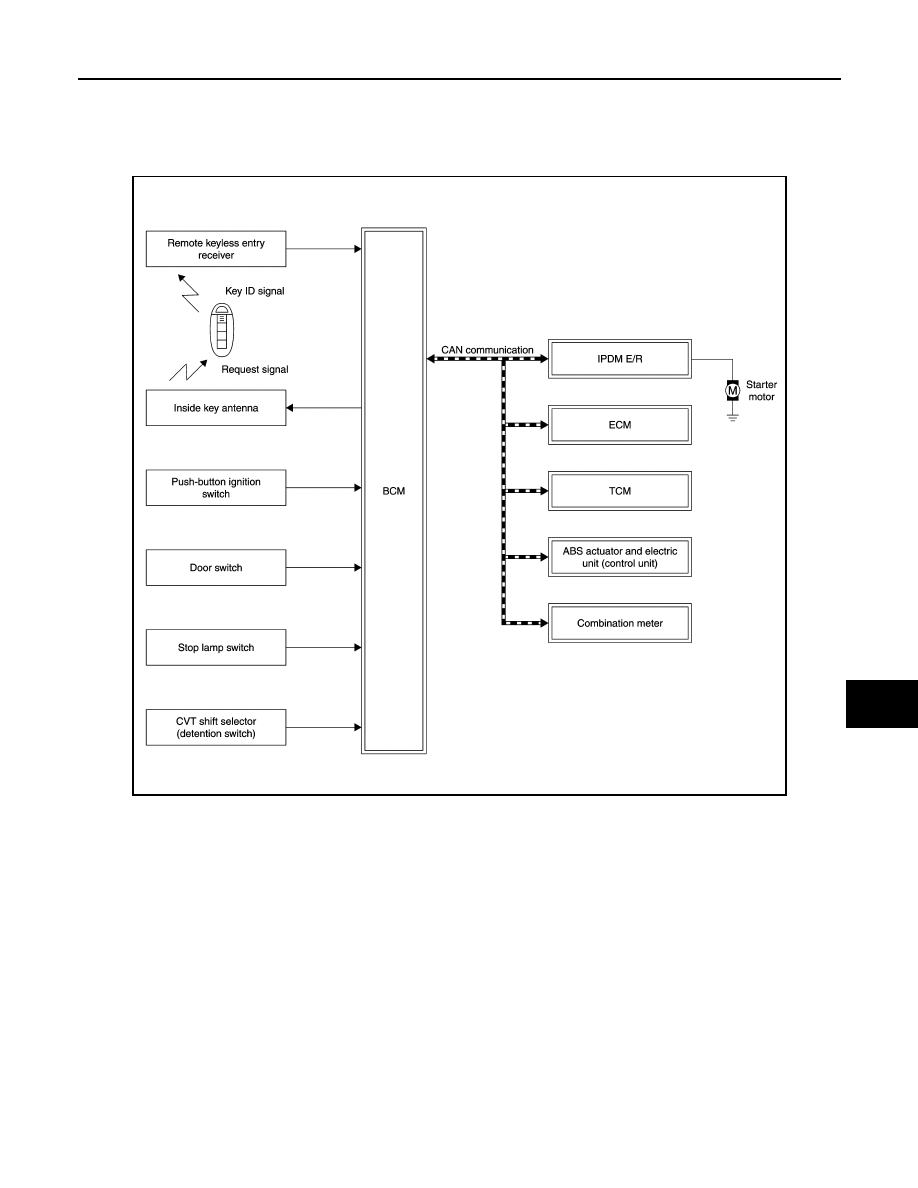
System Diagram
INFOID:0000000009722696
System Description
INFOID:0000000009722697
SYSTEM DESCRIPTION
• The engine start function of Intelligent Key system is a system that makes it possible to start and stop the
engine without removing the key. It verifies the electronic ID using two-way communications when pressing
the push-button ignition switch while carrying the Intelligent Key, which operates based on the results of
electronic ID verification for Intelligent Key using two-way communications between the Intelligent Key and
the vehicle.
NOTE:
The driver should carry the Intelligent Key at all times.
• Intelligent Key has 2 IDs [for Intelligent Key and for NVIS (NATS)]. It can perform the door lock/unlock oper-
ation and the push-button ignition switch operation when the registered Intelligent Key is carried.
• When the Intelligent Key battery is discharged, it can be used as emergency back-up by inserting the Intelli-
gent Key to the key slot. At that time, the NVIS (NATS) ID verification is performed. If it is used when the
Intelligent Key is carried, the Intelligent Key ID verification is performed.
• If the door lock/unlock operation is performed when the Intelligent Key battery is discharged, all doors lock/
unlock can be performed by operating the driver door key cylinder using the mechanical key set in the Intel-
ligent Key.
JMKIA6548GB
SEC-10
< SYSTEM DESCRIPTION >
[WITH INTELLIGENT KEY SYSTEM]
INTELLIGENT KEY SYSTEM/ENGINE START FUNCTION
• Intelligent Key can be registered up to 4 keys (Including the standard Intelligent Key) on request from the
owner.
NOTE:
• Refer to
DLK-18, "INTELLIGENT KEY SYSTEM : System Description"
for any functions other than engine
start function of Intelligent Key system.
PRECAUTIONS FOR INTELLIGENT KEY SYSTEM
• In the Intelligent Key system, the transponder [the chip for NVIS (NATS) ID verification] is integrated
into the Intelligent Key. (For the conventional models, it is integrated into the mechanical key.) There-
fore, the mechanical key cannot perform the ID verification, and thus it cannot start the engine.
Instead, the NVIS (NATS) ID verification can be performed by inserting the Intelligent Key into the key
slot, and then it can start the engine.
OPERATION WHEN INTELLIGENT KEY IS CARRIED
1.
When the push-button ignition switch is pressed, the BCM activates the inside key antenna and transmits
the request signal to the Intelligent Key.
2.
The Intelligent Key receives the request signal and transmits the Intelligent Key ID signal to the BCM.
3.
The BCM receives the Intelligent Key ID signal via remote keyless entry receiver, and verifies it with the
registered ID.
4.
BCM turns ACC relay ON and transmits the ignition power supply ON signal to IPDM E/R.
5.
IPDM E/R turns the ignition relay ON and starts the ignition power supply.
6.
BCM confirms that the shift position is P or N.
7.
BCM transmits the starter request signal via CAN communication to IPDM E/R and turns the starter relay
in IPDM E/R ON if BCM judges that the engine start condition is satisfied.
8.
IPDM E/R turns the starter control relay ON when receiving the starter request signal.
9.
Battery power is supplied through the starter relay and the starter control relay to operate the starter motor
and to start the cranking.
CAUTION:
If a malfunction is detected in the Intelligent Key system, the “KEY” warning lamp in the combina-
tion meter illuminates. At that time, the engine cannot be started.
10. When BCM received feedback signal from ECM acknowledging the engine has been initiated, the BCM
transmits a stop signal to IPDM E/R and stops the cranking by turning OFF the starter motor relay. (If the
engine initiating has failed, the cranking will stop automatically within 5 seconds.)
CAUTION:
When the Intelligent Key is carried outside of the vehicle (inside key antenna detection area) with
the power supply in ACC or ON position, even if the engine start condition* is satisfied, the engine
cannot be started.
*: For the engine start condition, refer to “POWER SUPPLY POSITION CHANGE TABLE BY PUSH-BUTTON
IGNITION SWITCH OPERATION”.
OPERATION RANGE
Engine can be started when Intelligent Key is inside the vehicle. However, sometimes engine might not start
when Intelligent Key is on instrument panel or in glove box.
OPERATION WHEN KEY SLOT IS USED
When the Intelligent Key battery is discharged, it performs the NVIS (NATS) ID verification between the inte-
grated transponder and BCM by inserting the Intelligent Key into the key slot, and then the engine can be
started.
For details relating to starting the engine using key slot, refer to
.
BATTERY SAVER SYSTEM
When all the following conditions are met for 60 minutes, the battery saver system will cut off the power supply
to prevent battery discharge.
• The ignition switch is in the ACC position
• All doors are closed
• Selector lever is in the P position
Reset Condition of Battery Saver System

INTELLIGENT KEY SYSTEM/ENGINE START FUNCTION
SEC-11
< SYSTEM DESCRIPTION >
[WITH INTELLIGENT KEY SYSTEM]
C
D
E
F
G
H
I
J
L
M
A
B
SEC
N
O
P
In order to prevent the battery from discharging, the battery saver system will cut off the power supply when all
doors are closed, the selector lever is in P position and the ignition switch is left on ACC position for 60 min-
utes. If any of the following conditions are met the battery saver system is released.
• Opening any door
• Operating with request switch on door lock
• Operating with Intelligent Key on door lock
Press push-button ignition switch and ignition switch will change to ACC position from OFF position.
POWER SUPPLY POSITION CHANGE TABLE BY PUSH-BUTTON IGNITION SWITCH OPERA-
TION
The power supply position changing operation can be performed with the following operations.
NOTE:
• When an Intelligent Key is within the detection area of inside key antenna and when it is inserted to the key
slot, it is equivalent to the operations below.
• When starting the engine, BCM checks the following conditions and then changes the power supply position.
- Brake pedal operating condition
- Selector lever position
- Vehicle speed
• This models do not have the steering lock system. However, power supply position changes to the LOCK
position without steering lock operation when the following conditions are fulfilled.
- Ignition switch: OFF
- Shift lever position: P
- Any of the following condition is met
• Opening door
• Closing door
• Door is locked by request switch operation
• Door is locked by Intelligent Key operation
Vehicle speed: less than 4 km/h (2.5 MPH)
Vehicle speed: 4 km/h (2.5 MPH) or more
Emergency stop operation
• Press and hold the push-button ignition switch for 2 seconds or more.
• Press the push-button ignition switch 3 times or more within 1.5 seconds.
Power supply position
Engine start/stop condition
Push-button ignition switch
operation frequency
Selector lever
Brake pedal operation
condition
LOCK
→
ACC
—
Not depressed
1
LOCK
→
ACC
→
ON
—
Not depressed
2
LOCK
→
ACC
→
ON
→
OFF
—
Not depressed
3
LOCK
→
START
ACC
→
START
ON
→
START
P or N position
Depressed
1
Engine is running
→
OFF
—
—
1
Power supply position
Engine start/stop condition
Push-button ignition switch
operation frequency
Selector lever
Brake pedal operation
condition
Engine is running
→
ACC
—
—
Emergency stop operation
Engine stall return operation while
driving
N position
Not depressed
1
SEC-12
< SYSTEM DESCRIPTION >
[WITH INTELLIGENT KEY SYSTEM]
INTELLIGENT KEY SYSTEM/ENGINE START FUNCTION
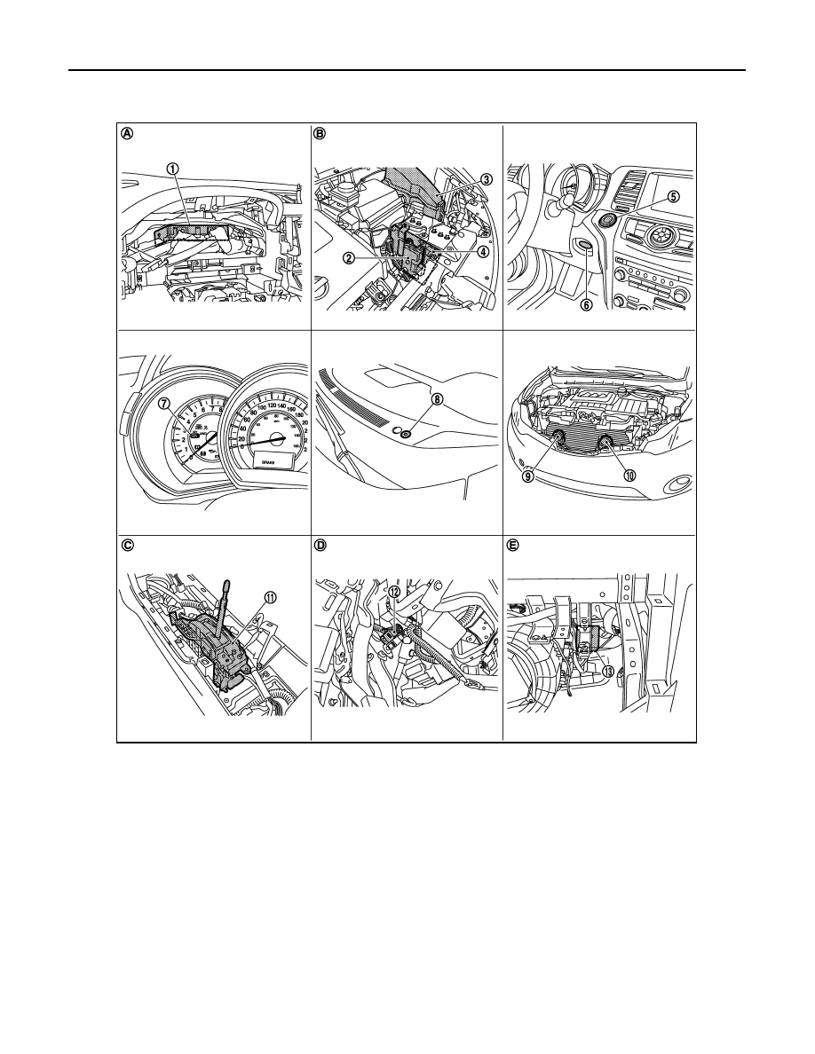
Component Parts Location
INFOID:0000000009722698
1.
BCM
2.
TCM
3.
IPDM E/R
4.
ECM
5.
Push-button ignition switch
6.
Key slot
7.
Combination meter (key warning lamp)
8.
Security indicator lamp
9.
Horn (high)
10. Horn (low)
11.
CVT shift selector (detention switch)
12. Stop lamp switch
13. Remote keyless entry receiver
A.
Behind the combination meter
B.
Engine room (LH)
C.
View with the center console as-
sembly removed
D.
Behind the instrument lower panel LH
E.
Behind the instrument lower panel RH
JMKIA1825ZZ
Нет комментариевНе стесняйтесь поделиться с нами вашим ценным мнением.
Текст