Nissan Murano. Manual — part 1509

WW-104
< ECU DIAGNOSIS INFORMATION >
IPDM E/R (INTELLIGENT POWER DISTRIBUTION MODULE ENGINE ROOM)
IHBT RLY -REQ
Ignition switch ON
Off
At engine cranking
On
ST/INHI RLY
Ignition switch ON
Off
At engine cranking
INHI ON
→
ST ON
The status of starter relay or starter control relay cannot be recognized by
the battery voltage malfunction, etc. when the starter relay is ON and the
starter control relay is OFF
UNKWN
DETENT SW
Ignition switch ON
• Press the selector button with se-
lector lever in P position
• Selector lever in any position oth-
er than P
Off
Release the selector button with selector lever in P position
On
S/L RLY -REQ
NOTE:
The item is indicated, but not monitored.
Off
S/L STATE
NOTE:
The item is indicated, but not monitored.
UNLOCK
DTRL REQ
NOTE:
The item is indicated, but not monitored.
Off
OIL P SW
Ignition switch OFF, ACC or engine running
Open
Ignition switch ON
Close
HOOD SW
NOTE:
The item is indicated, but not monitored.
Off
HL WASHER REQ
NOTE:
The item is indicated, but not monitored.
Off
THFT HRN REQ
Not operating
Off
• Panic alarm is activated
• Horn is activated with VEHICLE SECURITY (THEFT WARNING) SYS-
TEM
On
HORN CHIRP
Not operating
Off
Door locking with Intelligent Key (horn chirp mode)
On
CRNRNG LMP REQ
NOTE:
The item is indicated, but not monitored.
Off
Monitor Item
Condition
Value/Status
IPDM E/R (INTELLIGENT POWER DISTRIBUTION MODULE ENGINE ROOM)
WW-105
< ECU DIAGNOSIS INFORMATION >
C
D
E
F
G
H
I
J
K
M
A
B
WW
N
O
P
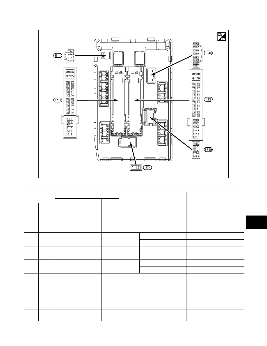
TERMINAL LAYOUT
PHYSICAL VALUES
JPMIA0863ZZ
Terminal No.
(Wire color)
Description
Condition
Value
(Approx.)
Signal name
Input/
Output
+
−
1
(R)
Ground
Battery power supply
Input
Ignition switch OFF
Battery voltage
2
(L)
Ground
Battery power supply
Input
Ignition switch OFF
Battery voltage
4
(LG)
Ground
Front wiper LO
Output
Ignition
switch ON
Front wiper switch OFF
0 V
Front wiper switch LO
Battery voltage
5
(Y)
Ground
Front wiper HI
Output
Ignition
switch ON
Front wiper switch OFF
0 V
Front wiper switch HI
Battery voltage
7
(GR)
Ground
Tail, license plate lamps &
illuminations
Output
Ignition
switch ON
Lighting switch OFF
0 V
Lighting switch 1ST
Battery voltage
10
(BR)
Ground
ECM relay power supply
Output
Ignition switch OFF
(More than a few seconds after turning
ignition switch OFF)
0 V
• Ignition switch ON
• Ignition switch OFF
(For a few seconds after turning igni-
tion switch OFF)
Battery voltage
12
(B)
Ground
Ground
—
Ignition switch ON
0 V
WW-106
< ECU DIAGNOSIS INFORMATION >
IPDM E/R (INTELLIGENT POWER DISTRIBUTION MODULE ENGINE ROOM)
13
(SB)
Ground
Fuel pump power supply
Output
Approximately 1 second or more after
turning the ignition switch ON
0 V
• Approximately 1 second after turning
the ignition switch ON
• Engine running
Battery voltage
15
(W)
Ground
Ignition relay power supply
Output
Ignition switch OFF
0 V
Ignition switch ON
Battery voltage
16
(R)
Ground
Front wiper auto stop
Input
Ignition
switch ON
Front wiper stop position
0 V
Any position other than
front wiper stop position
Battery voltage
19
(Y)
Ground
Ignition relay power supply
Output
Ignition switch OFF
0 V
Ignition switch ON
Battery voltage
20
(L)
Ground
Ambient sensor ground
Output
Ignition switch ON
0 V
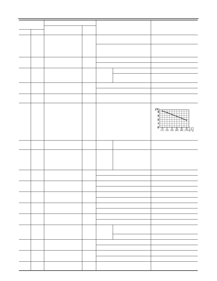
21
(O)
Ground
Ambient sensor
Input
Ignition switch ON
NOTE:
Changes depending to ambient tem-
perature
22
(SB)
Ground
Refrigerant pressure sen-
sor ground
Output
Engine
running
• Warm-up condition
• Idle speed
0 V
23
(GR)
Ground
Refrigerant pressure sen-
sor
Output
Engine
running
• Warm-up condition
• Both A/C switch and
blower fan motor switch
ON
(Compressor operates)
1.0 - 4.0 V
24
(G)
Ground
Refrigerant pressure sen-
sor power supply
Input
Ignition switch OFF
0 V
Ignition switch ON
5.0 V
25
(GR)
Ground
Ignition relay power supply
Output
Ignition switch OFF
0 V
Ignition switch ON
Battery voltage
26
*1
(Y)
Ground
Ignition relay power supply
Output
Ignition switch OFF
0 V
Ignition switch ON
Battery voltage
27
(W)
Ground
Ignition relay monitor
Input
Ignition switch OFF or ACC
Battery voltage
Ignition switch ON
0 V
28
(SB)
Ground
Push-button ignition
switch
Input
Press the push-button ignition switch
0 V
Release the push-button ignition switch
Battery voltage
30
(BR)
Ground
Starter relay control
Input
Ignition
switch ON
Selector lever in any posi-
tion other than P or N
0 V
Selector lever P or N
Battery voltage
34
(O)
Ground
Cooling fan relay-3 control
Input
Cooling fan stopped
Battery voltage
Cooling fan at HI operation
0 V
35
(P)
Ground
Cooling fan relay-1 power
supply
Input
Cooling fan stopped
Battery voltage
Cooling fan at LO operation
6.0 V
36
(G)
Ground
Battery power supply
Input
Ignition switch OFF
Battery voltage
Terminal No.
(Wire color)
Description
Condition
Value
(Approx.)
Signal name
Input/
Output
+
−
JSNIA0014GB

IPDM E/R (INTELLIGENT POWER DISTRIBUTION MODULE ENGINE ROOM)
WW-107
< ECU DIAGNOSIS INFORMATION >
C
D
E
F
G
H
I
J
K
M
A
B
WW
N
O
P
38
(GR)
Ground
Cooling fan relay-1 power
supply
Output
Cooling fan not operating
0 V
Cooling fan at LO operation
6.0 V
39
(P)
—
CAN-L
Input/
Output
—
—
40
(L)
—
CAN-H
Input/
Output
—
—
41
(B)
Ground
Ground
—
Ignition switch ON
0 V
42
(SB)
Ground
Cooling fan relay-2 control
Input
Cooling fan stopped
Battery voltage
• Cooling fan MID operating
• Cooling fan HI operating
0 V
43
(Y)
Ground
CVT shift selector
(Detention switch)
Input
Ignition
switch ON
• Press the selector but-
ton (selector lever P)
• Selector lever in any po-
sition other than P
Battery voltage
Release the selector but-
ton (selector lever P)
0 V
44
(W)
Ground
Horn relay control
Input
The horn is deactivated
Battery voltage
The horn is activated
0 V
45
(G)
Ground
Horn switch
Input
The horn is deactivated
Battery voltage
The horn is activated
0 V
46
(BR)
Ground
Starter relay control
Input
Ignition
switch ON
Selector lever in any posi-
tion other than P or N
0 V
Selector lever P or N
Battery voltage
48
(W)
Ground
A/C relay power supply
Output
Engine
running
A/C switch OFF
0 V
A/C switch ON
(A/C compressor is oper-
ating)
Battery voltage
49
(R/B)
Ground
ECM relay power supply
Output
Ignition switch OFF
(More than a few seconds after turning
ignition switch OFF)
0 V
• Ignition switch ON
• Ignition switch OFF
(For a few seconds after turning igni-
tion switch OFF)
Battery voltage
51
(LG)
Ground
Ignition relay power supply
Output
Ignition switch OFF
0 V
Ignition switch ON
Battery voltage
52
(Y/G)
Ground
Ignition relay power supply
Output
Ignition switch OFF
0 V
Ignition switch ON
Battery voltage
53
(R/W)
Ground
ECM relay power supply
Output
Ignition switch OFF
(More than a few seconds after turning
ignition switch OFF)
0 V
• Ignition switch ON
• Ignition switch OFF
(For a few seconds after turning igni-
tion switch OFF)
Battery voltage
Terminal No.
(Wire color)
Description
Condition
Value
(Approx.)
Signal name
Input/
Output
+
−
Нет комментариевНе стесняйтесь поделиться с нами вашим ценным мнением.
Текст