Nissan Murano. Manual — part 469
DIFFERENTIAL ASSEMBLY
DLN-115
< UNIT DISASSEMBLY AND ASSEMBLY >
[REAR FINAL DRIVE: R145]
C
E
F
G
H
I
J
K
L
M
A
B
DLN
N
O
P
4.
Align the lock pin holes on differential case with shaft, and install
pinion mate shaft.
5.
Measure side gear end play following the procedure below, and select the appropriate side gear thrust
washers.
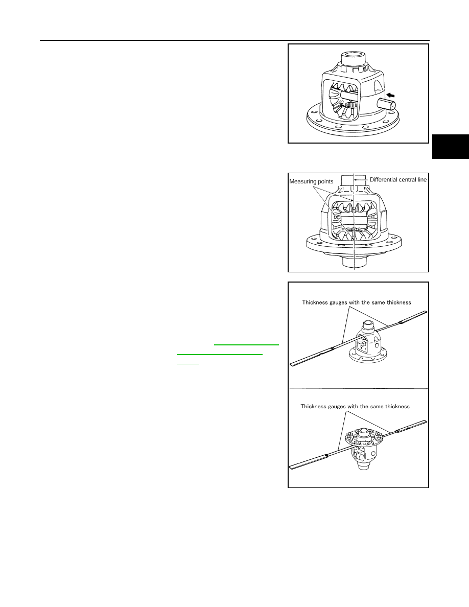
a.
Place differential case straight up so that side gear to be mea-
sured comes upward.
b.
Using thickness gauges, measure the clearance between side
gear back and differential case at 3 different positions, while
rotating side gear. Average the 3 readings, and then decide the
clearance. (Measure the clearance of the other side as well.)
CAUTION:
To prevent side gear from tilting, insert thickness gauges
with the same thickness from both sides.
c.
If the back clearance is outside the specification, use a thicker/
thinner side gear thrust washer to adjust. For selecting thrust
washer, refer to the latest parts information.
CAUTION:
Select a side gear thrust washer for right and left individually.
SDIA0037J
PDIA0460E
Standard
Side gear back clearance
When the back clearance is large:
Use a thicker thrust washer.
When the back clearance is small:
Use a thinner thrust washer.
SDIA0583E
DLN-116
< UNIT DISASSEMBLY AND ASSEMBLY >
[REAR FINAL DRIVE: R145]
DIFFERENTIAL ASSEMBLY
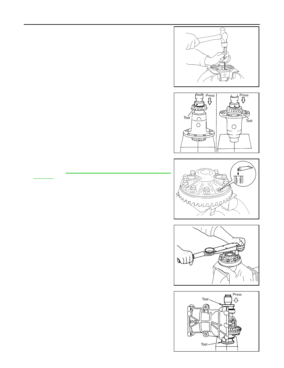
6.
Drive a lock pin into pinion mate shaft, using the pin punch.
CAUTION:
Never reuse lock pin.
7.
Press side bearing inner races to differential case, using the drift
[SST: KV40105020 (
—
)].
CAUTION:
Never reuse side bearing inner races.
8.
Apply locking sealant into the thread hole of drive gear.
Use Genuine High Strength Thread Locking Sealant or equiva-
lent. Refer to
GI-22, "Recommended Chemical Products and
.
CAUTION:
The drive gear back and threaded holes shall be cleaned
and decreased sufficiently.
9.
Install drive gear to the differential case, and then tighten to the
specified torque.
10. Apply gear oil to side bearings, and install new side bearing
adjusting shims (2 pieces for one side) with the same thickness
as the ones installed prior to disassembly or re-install the old
ones, with side bearing outer race to differential case.
If side bearing adjusting shims have been already selected, use
them.
CAUTION:
Never reuse side bearing outer race.
11. Set the drifts [SST: KV40100610 (J-26089)] to the right and left
side bearing adjusting shims individually. Compress differential
case assembly and side bearing to install gear carrier assembly
to differential case assembly.
CAUTION:
• The drift shall be placed on the center of the adjusting
shims.
• The pressure shall be as low as possible to install differ-
ential assembly into gear carrier assembly. The maximum
pressure shall be 10 kN (1 ton, 1.1 US ton, 1.0 Imp ton).
• If the adjusting shims are installed by tapping, the gear
carrier may be damaged. Avoid tapping.
PDIA0759J
PDIA0052E
SPD554
PDIA0466E
PDIA0064E
DIFFERENTIAL ASSEMBLY
DLN-117
< UNIT DISASSEMBLY AND ASSEMBLY >
[REAR FINAL DRIVE: R145]
C
E
F
G
H
I
J
K
L
M
A
B
DLN
N
O
P
12. Install dummy cover set, check and adjust drive gear runout, tooth contact, backlash, and total preload
13. Remove dummy cover set.
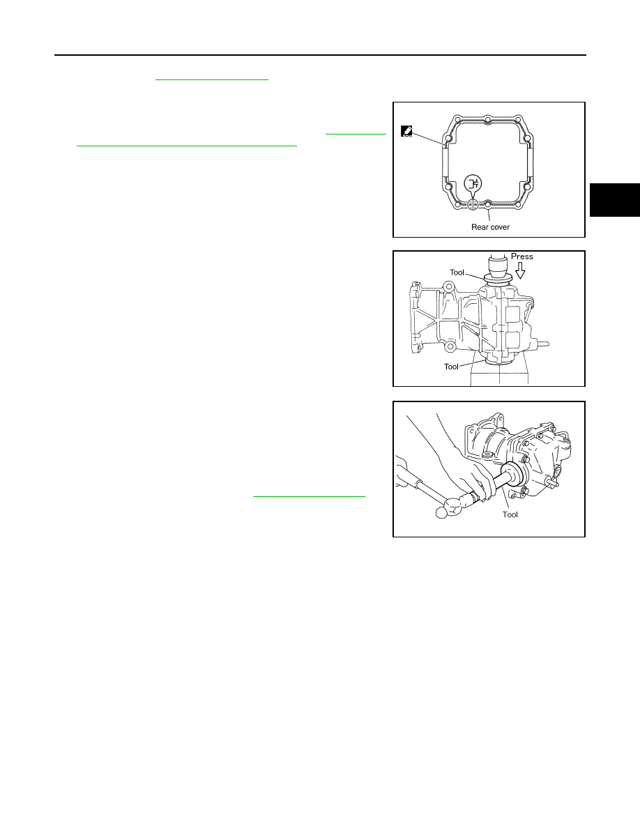
14. Apply liquid gasket to mating surface of rear cover. Overlap both
ends of the bead for at least 3 mm (0.12 in).
Use Genuine Silicone RTV or equivalent. Refer to
ommended Chemical Products and Sealants"
CAUTION:
Remove old gasket adhering to the mounting surfaces.
Also remove any moisture, oil, or foreign material adhering
to the mounting surfaces.
15. Set the drifts [SST: KV40100610 (J-26089)] to the right and left
side bearing adjusting shims individually. Compress differential
case assembly and side bearing to install rear cover.
CAUTION:
• The drift shall be placed on the center of the adjusting
shims.
• The pressure shall be as low as possible to install the rear
cover. The maximum pressure shall be 10 kN (1 ton, 1.0
Imp ton).
• If rear cover is forced in by tapping, rear cover may be
damaged by adjusting shims. Avoid tapping.
16. Tighten rear cover mounting bolts to the specified torque.
17. Using the drift [SST: KV38100200 (J-26233)], drive side oil seals
until it becomes flush with the carrier end.
CAUTION:
• Never reuse oil seals.
• When installing, do not incline oil seals.
• Apply multi-purpose grease onto oil seal lips, and gear oil
onto the circumference of oil seal.
18. Check total preload torque. Refer to
.
Inspection After Disassembly
INFOID:0000000009718198
DRIVE GEAR AND DRIVE PINION
• Clean up the disassembled parts.
• If the gear teeth never mesh or line-up correctly, determine the cause and adjust or replace as necessary.
• If the gears are worn, cracked, damaged, pitted or chipped (by friction) noticeably, replace with new drive
gear and drive pinion as a set.
BEARING
• Clean up the disassembled parts.
• If any chipped (by friction), pitted, worn, rusted or scratched marks, or unusual noise from the bearing is
observed, replace as a bearing assembly (as a new set).
SIDE GEAR AND PINION MATE GEAR
• Clean up the disassembled parts.
• If any cracks or damage on the surface of the tooth is found, replace.
• If any worn or chipped mark on the contact sides of the thrust washer is found, replace.
SIDE GEAR THRUST WASHER AND PINION MATE THRUST WASHER
• Clean up the disassembled parts.
• If it is chipped (by friction), damaged, or unusually worn, replace.
PDIA0447E
PDIA0065E
PDIA0448E
DLN-118
< UNIT DISASSEMBLY AND ASSEMBLY >
[REAR FINAL DRIVE: R145]
DIFFERENTIAL ASSEMBLY
OIL SEAL
• Whenever disassembled, replace.
• If wear, deterioration of adherence (sealing force lips), or damage is detected on the lips, replace them.
DIFFERENTIAL CASE
• Clean up the disassembled parts.
• If any wear or crack on the contact sides of the differential case is found, replace.
COMPANION FLANGE
• Clean up the disassembled parts.
• If any chipped mark [about 0.1 mm, (0.004 in)] or other damage on the contact sides of the lips of the com-
panion flange is found, replace.
Нет комментариевНе стесняйтесь поделиться с нами вашим ценным мнением.
Текст