Nissan Murano. Manual — part 274
RADIATOR
CO-17
< REMOVAL AND INSTALLATION >
C
D
E
F
G
H
I
J
K
L
M
A
CO
N
P
O
Removal and Installation
INFOID:0000000009720483
REMOVAL
WARNING:
Never remove radiator cap when engine is hot. Serious burns could occur from high-pressure engine
coolant escaping from radiator. Wrap a thick cloth around the cap. Slowly turn it a quarter of a turn to
release built-up pressure. Carefully remove radiator cap by turning it all the way.
NOTE:
When removing components such as hoses, tubes/lines, etc., cap or plug openings to prevent fluid from spill-
ing.
1.
Remove the following parts:
• Engine under cover.
• Radiator core support covers (RH and LH): Refer to
.
• Air duct (inlet): Refer to
.
• Front grille: Refer to
• Horn: Refer to
.
• Hood lock: Refer to
2.
Drain engine coolant from radiator. Refer to
CAUTION:
• Perform this step when the engine is cold.
• Never spill engine coolant on drive belt.
3.
Disconnect reservoir tank hose from radiator pipe (upper).
4.
Disconnect CVT fluid cooler hoses from radiator.
• Install blind plug to avoid leakage of CVT fluid.
5.
Remove radiator cap adapter and each radiator hoses (upper) and radiator pipe (upper) assembly.
CAUTION:
Be careful not to allow engine coolant to contact drive belt.
6.
Disconnect radiator hose (lower) from radiator.
7.
Remove condenser. Refer to
.
CAUTION:
Be careful not to damage condenser core.
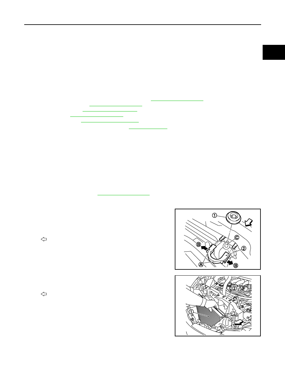
8.
Remove each radiator upper clips (2) by pulling the tabs (A) out-
side to release the lock (B) and then remove each mounting rub-
bers (upper) (1).
CAUTION:
Never pull the tabs outside excessively to prevent it from
damping.
9.
Lift up and remove radiator (1) from front of radiator core support
(2).
CAUTION:
Be careful not to damage or scratch on radiator core.
INSTALLATION
CAUTION:
Do not reuse O-rings.
C
: Mounting pin
: Vehicle front
JPBIA1689ZZ
: Vehicle front
JPBIA1699ZZ
CO-18
< REMOVAL AND INSTALLATION >
RADIATOR
Note the following, and install in the reverse order of removal.
Radiator Upper Clip
Install each radiator upper clips on radiator core connection as follows:
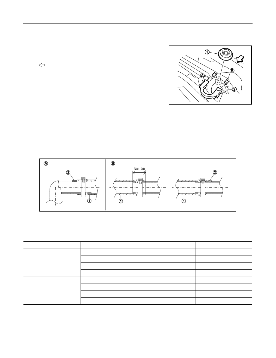
1.
Install each mounting rubbers (upper) (1) on mounting pins (A)
of radiator.
2.
Align each radiator upper clips (2) with radiator core connection
(B), then insert each radiator upper clips straight into radiator
core connections until a click is heard.
3.
After connecting each radiator upper clips, use the following
method to check it is fully connected.
• Visually confirm that each radiator upper clips are connected
to radiator core connections.
• Move each radiator upper clips and the radiator forward and backward to check they are securely con-
nected.
Radiator hose
CAUTION:
• Use genuine mounting bolts for the cooling fan assembly and strictly observe the tightening torque.
(Breakage prevention for radiator)
NOTE:
• Insert the radiator hose (1) all the way to the stopper (2) or by 33 mm (1.30 in) (hose without a stopper).
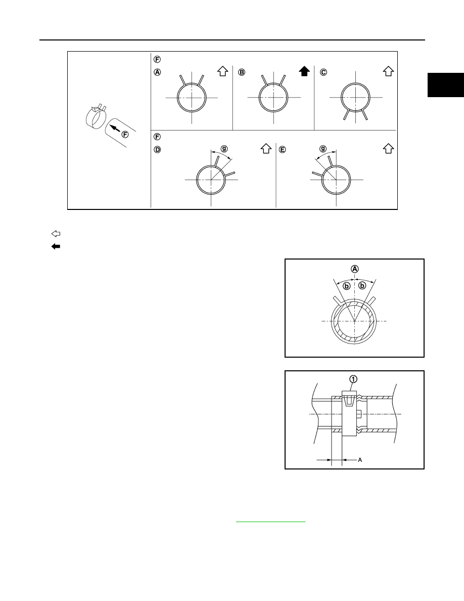
• For the orientation of the hose clamp pawl, refer to the figure.
*Refer to the illustrations for the specific position each hose clamp tab.
: Vehicle front
JPBIA1690ZZ
Unit mm (in)
A.
Radiator side
B.
Engine side
JPBIA4294GB
Radiator hose
Hose end
Paint mark
Position of hose clamp*
Radiator hose (upper)
Radiator side
Right side
C
Radiator pipe radiator side
No marking
B
Radiator pipe engine side
No marking
C
Engine side
Upper
D
Radiator hose (lower)
Radiator side
Upper
A
Radiator pipe radiator side
No marking
A
Radiator pipe engine side
No marking
A
Engine side
Upper
E
RADIATOR
CO-19
< REMOVAL AND INSTALLATION >
C
D
E
F
G
H
I
J
K
L
M
A
CO
N
P
O
• The angle (b) created by the hose clamp pawl and the specified
line (A) must be within
±
30
°
as shown in the figure.
• To install hose clamps (1), check that the dimension (A) from the
end of the hose clamp on the radiator hose to the hose clamp is
within the reference value.
Inspection
INFOID:0000000009720484
INSPECTION AFTER INSTALLATION
• Check for leakage of engine coolant using the radiator cap tester adapter (commercial service tool) and the
radiator cap tester (commercial service tool). Refer to
• Start and warm up the engine. Visually check that there is no leakage of engine coolant and CVT fluid.
F.
View F
g.
45
°
Vehicle upper
Vehicle rear
JPBIA4777ZZ
JPBIA4295ZZ
Dimension “A”
: 3 – 7 mm
: 0.12 – 0.28 in
JPBIA3527ZZ
CO-20
< REMOVAL AND INSTALLATION >
COOLING FAN
COOLING FAN
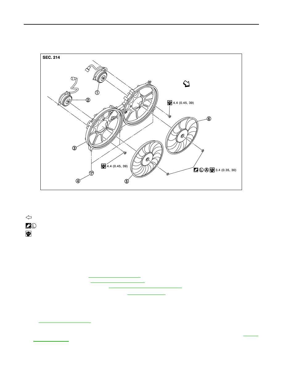
Exploded View
INFOID:0000000009720485
Removal and Installation
INFOID:0000000009720486
REMOVAL
1.
Remove the following parts.
• Engine under cover
• Air duct (inlet): Refer to
.
• Oil level gauge: Refer to
• Battery and battery tray: Refer to
PG-97, "Removal and Installation"
2.
Drain engine coolant from radiator. Refer to
CAUTION:
• Perform this step engine is cold.
• Never spill engine coolant on drive belt.
3.
Remove radiator cap adapter and each radiator hoses (upper) and radiator pipe (upper) assembly. Refer
to
.
4.
Disconnect harness connector from fan motors (RH and LH), and move harness to aside.
5.
Disconnect harness connector from crash zone sensor, and move harness to aside. Refer to
6.
Remove battery tray bracket mounting bolts, and move battery tray bracket to aside.
1.
Fan motor (LH)
2.
Fan motor (RH)
3.
Fan shroud
4.
Mounting rubber
5.
Cooling fan (RH)
6.
Cooling fan (LH)
A.
Apply on fan motor shaft
: Vehicle front
: Apply genuine high strength thread locking sealant or equivalent.
: N·m (kg-m, in-lb)
JPBIA1687GB
Нет комментариевНе стесняйтесь поделиться с нами вашим ценным мнением.
Текст